• The move to the new server is done. There are some software and database maintenance updates in process. This has us passing the hat around to help out. We appreciate any donations. Seriously, even a dollar helps. The payment page may be found here - https://www.audiokarma.org/support.html

Altec Model 14 troubleshooting help

Seems there is an intermittent/loose/tarnished connection that needs attention. Cold solder connections or just a poor/loose connection in the wiring from the crossover to the speaker could explain what you are hearing. Cant remember for sure if the connections to the horn driver are push on but I believe they are. You can use an ohm meter between the solder point where the wires connect to the crossover and the tab on the horn driver. You should only see less than .1 ohms between these points.

So make sure the push on connectors are not to loose and have a decent grip on the tab at the horn driver. Be GENTLE and Inspect the tab and push on connectors for any type of tarnish or corrosion. They should be clean, tarnish or loose connections will cause added resistance reducing sound levels. Deoxit and a gentle cleaning of the tab and push on connector may cure this issue. You can also replace the push on connectors with new of the same size with basic hand tools.
Thanks for the reply and ideas! I'll check this tomorrow. The speakers do indeed have spade terminals but I think the connectors are tight. I'll double check and test with an ohm meter as well. To confirm, are you recommending to test the wires from the female connector (that connects to the speaker) to the other end (solder joint on the board) to test the impedance of that wire? If so, I hadn't thought to try that, that's a good idea. I mentioned above that there is a different resistance between the right and left horn. One tests 6.5ohm and the other 7.5. Is this a big enough difference to create the issue do you think?

And you've determined that it's not the room acoustics causing all of this, right? You're sure there not some sort of room reflection somewhere? What is the room like? I can tell you for a fact I've had that happen in the past, and especially with no room treatments, plus we don't know what your room looks like. I've had issues with speakers being to close to ceiling fans and I could hear the sound reflecting off the fan blades till I turned the fan off. But definitely clean those pots as they can cause a lot of issues, too.

@damacman
So I finally moved speakers and flipped right speaker with left (had to muster up the willpower to move these beasts). It made a very slight difference, but definetly was not the main issue. Iv rearranged the room a bit as well to even out the room reflections as much as I can too.

I also ran brand new speaker wire to each speaker with no change. Currently I have everything back together to do a little listening and have just made adjustments to the pots and my amps to even out the sound as best I can but it's still noticable.. ill order some new wire to match the gage installed by Altec to re run the questionable wires but that will take a while to get and install... more updates to come though and any ideas yall have are always appreciated!
 
Last edited:
Thanks for the reply and ideas! I'll check this tomorrow. The speakers do indeed have spade terminals but I think the connectors are tight. I'll double check and test with an ohm meter as well. To confirm, are you recommending to test the wires from the female connector (that connects to the speaker) to the other end (solder joint on the board) to test the impedance of that wire? If so, I hadn't thought to try that, that's a good idea. I mentioned above that there is a different resistance between the right and left horn. One tests 6.5ohm and the other 7.5. Is this a big enough difference to create the issue do you think?


So I finally moved speakers and flipped right speaker with left (had to muster up the willpower to move these beasts). It made a very slight difference, but definetly was not the main issue. Iv rearranged the room a bit as well to even out the room reflections as much as I can too.

I also ran brand new speaker wire to each speaker with no change. Currently I have everything back together to do a little listening and have just made adjustments to the pots and my amps to even out the sound as best I can but it's still noticable.. ill order some new wire to match the gage installed by Altec to re run the questionable wires but that will take a while to get and install... more updates to come though and any ideas yall have are always appreciated!

Yes this test will show the resistance of the wires and the solder connections to the board. Try to get the meter test lead/probe on the male tab on the speaker with the spade connector still in place. Test both wires this way to each speaker connection. If you can do that then you will be reading the wire to spade connector and the spade to speaker tab resistance as well. Test both speakers the same way and compare the readings. If you can select a range with your meter select the lowest range for ohms.

If you have a poor connection it will show as a higher resistance. Make sure your test leads are making good contact with the points you are testing a little pressure is ok. Right each reading down then double check your tests to confirm the readings.
 
@Qbert909

You should make sure that your M14's have identical crossovers ( sporting the same layout + value of capacitors )

The M14 went through multiple versions of these crossovers ( according to older posts made by Richard C ) ..

Changing the value of those caps will noticeably change the voicing of the speaker.

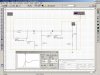
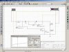
Here are 2 simplified versions ( these diagrams are missing the protection circuit and the drivers themselves are represented by substituted RL values )


model_14_crossover_6_uf_67mh.JPG
model_14_crossover_10uf_hf.jpg

:)
 
Last edited:
Hey guys, sorry for taking so long to post back on here. Iv gotten real busy at work so Iv had little to no time to enter the listening room to work on or listen to anything.


Yes this test will show the resistance of the wires and the solder connections to the board. Try to get the meter test lead/probe on the male tab on the speaker with the spade connector still in place. Test both wires this way to each speaker connection. If you can do that then you will be reading the wire to spade connector and the spade to speaker tab resistance as well. Test both speakers the same way and compare the readings. If you can select a range with your meter select the lowest range for ohms.

If you have a poor connection it will show as a higher resistance. Make sure your test leads are making good contact with the points you are testing a little pressure is ok. Right each reading down then double check your tests to confirm the readings.
Im hopeful Ill have time to try this tomorrow after work and will report back with what I find. I also have new wire so I may test and run new main wires from the terminals to the bords (since i know at least one of them to be questionable).

@Qbert909

You should make sure that your M14's have identical crossovers ( sporting the same layout + value of capacitors )

The M14 went through multiple versions of these crossovers ( according to older posts made by Richard C ) ..

Changing the value of those caps will noticeably change the voicing of the speaker.

Here are 2 simplified versions ( these diagrams are missing the protection circuit and the drivers themselves are represented by substituted RL values )


View attachment 2620094
View attachment 2620095

:)
I did confirm that the crossovers and capacitor values are the same between both speakers. They each have the version with 2x 6uf and 1x 2uf capacitors which I replaced with the same value and quantity AudioCap PPT Theta caps (2x 6uf & 1x 2uf per crossover). I also tested each cap and they all tested within spec so I dont think its a capacitor issue at this point but I could be wrong. I was wondering if the inductor could be out of spec but Im kind of just guessing at this point and dont see an easy way to test it with a quick google search.

There was a difference between the HF driver resistance that I mentioned above between the two speakers however - Im just unsure if this would cause the difference in sound im hearing and what could be done to fix the issue. Im not sure I understand how driver resistance would change over time either?

Thanks everyone for your continued support and ideas! Yall are awesome and very helpful!
 
So I finally had a spare hour to sit down to work on this problem a little. After getting the wrong gauge wire 2x, I finally got the right gauge to match factory and replaced the + and - wires from the terminals on the muted sounding speaker to the board. Previously the - wire when moved a certain way caused the speaker to cut out. With that issue fixed I put everything back together and tested the speaker but no change. Still the same issue persists.


Yes this test will show the resistance of the wires and the solder connections to the board. Try to get the meter test lead/probe on the male tab on the speaker with the spade connector still in place. Test both wires this way to each speaker connection. If you can do that then you will be reading the wire to spade connector and the spade to speaker tab resistance as well. Test both speakers the same way and compare the readings. If you can select a range with your meter select the lowest range for ohms.

If you have a poor connection it will show as a higher resistance. Make sure your test leads are making good contact with the points you are testing a little pressure is ok. Right each reading down then double check your tests to confirm the readings.
@300man - I tried performing this test but my multimeter reported "OL" for overload I think. I'm probably doing something wrong I think but I'm unsure - do I need to unsolder the wire from the crossover board to accurately test the resistance of the wire only? If I test from one end of the wire to the other while connected to the crossover board does that test the resistance of the entire connected system (the board and all connected signal path)? Sorry if this is a dumb question - I'm learning as I go so forgive my ignorance. I have no issue unsoldering all the wires and replacing if necessary - just trying to narrow the issue instead of a shotgun approach so I learn how to troubleshoot future issues.

As I previously mentioned, the right and left horns tested different - with them completely disconnected from the system. I'm not sure if this could cause the issues I'm hearing or how to fix it though. any ideas?

Thanks guys! Sorry for the delays in posting lately, thanks for yall's continued input and support!
 
Last edited:
It could be that the horns have different diaphragms. I'd recommend swapping horns between the speakers and see if the problem follows the horn but your original post says you've already done that ... even yet, it's worth a gander.

Don't overlook the HF protection circuit for the horns. This has been well documented in other threads here and at Lansing Heritage.
 
Resistors can also cause your symptoms. If you have sand cast resistors or any other type you should check to see if they're in spec
 
Thank you all for your help, sorry for my absence. The time I have available to focus on this stuff swings between a lot and none quite drastically (often settling on none).

I currently have the Altecs back together with the pots adjusted to even everything out - I suppose thats one use case for the pots after all.

It could be that the horns have different diaphragms. I'd recommend swapping horns between the speakers and see if the problem follows the horn but your original post says you've already done that ... even yet, it's worth a gander.

Don't overlook the HF protection circuit for the horns. This has been well documented in other threads here and at Lansing Heritage.

I have read about the protection circuit - I'm on the fence about bypassing to test per the heritage guidelines as it appears it involves changing some things from the original design but I suppose its worth a shot especially if Im going to replace the resisters... I may endeavor to do this in the future.

For the test I mentioned you do not unsolder the wire, keep everything together.

I have not tried this test yet as I have had everything back together before I fully understood the method. I will also try this sometime in the future.

Resistors can also cause your symptoms. If you have sand cast resistors or any other type you should check to see if they're in spec

I was unsure as to whether or not the resistors could contribute to this issue, thanks for your input. Replacements seem to be pretty cheap and fairly available - this will probably be the first thing I try as far as future crossover changes (before protection bypass that is).

These tests and next steps may take me a while to get to however as I just picked up 2 more pairs of speakers this afternoon - a pair of ESS AMT-1a and a pair of Sony SS-7600 ULM speakers. I have pretty much maxed out my capacity for the room things are in so until I expand to another room or purge, working on things will be exceedingly difficult.

I am still planning to stick to my promise to keep updating this thread when I do any work in the future and searching for the core issue that I'm experiencing. I was initially hoping it would be a few weeks or a month endeavor, but this will probably be more like month(s) for full transparency. Thanks for yalls help - Ill continue to update as I try things.
 
I mentioned above that there is a different resistance between the right and left horn. One tests 6.5ohm and the other 7.5. Is this a big enough difference to create the issue do you think?
It's a big enough difference to suggest one of the phragms is NOT a genuine Altec, or there's something wrong with it. 7.5 is too high for a healthy 8 ohm Altec made diaphragm.

It could be that the horns have different diaphragms.
This would have been, empirically, the first thing to verify once a 1 ohm discrepancy in DCR was established.
 
The earlier 14's and the later 14's used a different design on the phase plug
That is not correct.

Here is an exploded view of the entire assembly if that helps.
That's an Alnico 802 with 1 inch throat, discontinued a year or two before the model 14 was introduced.

The model 14 used a bare bones version(no rear chamber/cover, just a loading cap) of the 902 with a 7/8 inch throat to mate properly with the 7/8 inch throat of it's Mantaray horn.
 
reviving this thread for an identical issue with my model 14's.
One horn is brighter/louder than the other. Much swapping has tied it to this driver.
Horns are identical with orange tangerine phase plugs, crossovers are good and played fine for years.
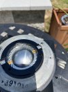
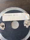
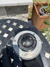
This as far as I could break down the driver without brute force.
appears fine except for some light marks at the 4 o'clock and 11 o'clock positions.
I would replace it but don't see anything OEM currently available online or at Great Plains Audio.
I verified and swapped phase...I'm stumped. These did take a power surge from a electrical storm. Maybe internally damaged.

Any help is appreciated.
902-1.jpeg902-2.jpeg902-3.jpeg
 
The horn with issues reads 7.4 ohms. I snagged a OEM replacement on the Bay and everything came back to life. I cannot figure out why this unit is playing lower and with less clarity, but something is certainly wrong with it.
 
Back
Top Bottom