• The move to the new server is done. There are some software and database maintenance updates in process. This has us passing the hat around to help out. We appreciate any donations. Seriously, even a dollar helps. The payment page may be found here - https://www.audiokarma.org/support.html

Am I checking the Bias right? Sansui 990

Devileyes

Member
My 990 has been running hot since I bought it a few months ago. It’s been recapped and had the trim pots replaced by the dude who I bought it from.
Anyway I checked the DC offset first, using the SM and the sticky thread. RC was 37.0 and LC was 8.9. I adjusted those both down to as close to 0 as I could.
Now when checking the Bias it is way high in both channels. I shut everything down and re-read everything to make sure I was doing it right.
Tried again, but still getting 61.17 in the RC and
110.3 in the LC.
I adjusted both down, but the lowest I could get either was 45-47 when I ran out of turning on the trim pots.
I was thinking that they were set at 50 by the seller and was going to try to adjust to 30 since I’ve read that 50 for the 9090/990 may be a misprint.
Anyway after adjusting both down all the way to 45-47 I ran it for a few hours and it was barely warm. Before it would heat up in about 10 to 15 minutes and get so hot in the middle of the heat sink on the back that you could barely touch it.
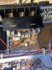
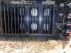
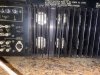
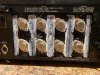
I’m including pics of my MM and the connectors on the fuse holders. The fuses were pulled for each test. I am just using a blown fuse connector I made for the leads, as I don’t trust my shakes hands.
Thanks for listening!
Joe1BDDCA88-F80F-4B95-A20F-C86DC1B730D5.jpeg816E6558-A1F0-4842-9A3D-2DA7F60E941C.jpeg492538F2-1D83-40D9-A790-40FD4A361AC9.jpegE5BAD516-DA82-4B9C-9D3C-1F0E90384F9A.jpeg
 
Register to hide this ad
I hope you're on DBT? 50mA is correct for 990/9090 but set it a few mA lower on DBT b/c it will rise on mains voltage. Yeah, it looks right. Make sure all the driver amp fuseable resistors are in spec and hadn't drifted and try to replace the VD1212 red ball diodes with a couple 1n4148 in series for each. Try it again then.
 
50 is for the 9090. You can’t set it on the dim bulb—it should be plugged into the wall. The driver board should be fully rebuilt with the fuse resistors, glass bead diodes, and differential transistors replaced.
 
Last edited:
You can’t set it on the dim bulb—it should be plugged into the wall.
yes, that is true but one of the chief causes for blowing outputs and frying driver amps is this specific routine. Performed between the confined space of the PS fuses, in proximity to conducting components of the driver amp, subject to confusion between the DC offset and bias trimmers and faults, in addition to a possible blown meter fuse in measuring current in series, makes this routine extremely risky with the XX0/X0X0 series of recievers. It's best to always perform the bias routine on DBT and dial it about 3mA bellow the threshold. Then, when all is good and safe, one can move the power cord to the wall with all other measurement leads and probes in place and to finalize the settings with minimum hassle.

BTW, that's why many here prefer to take a voltage measurement across the emitter resistors and calculate the current by Ohm's law.
 
Thanks for the replies guys!
It’s not on a DBT at the moment, but I will consider doing it that way from now on, as I have built one and have been using it regularly.
One of the reasons I built the spent fuse adapter is to eliminate the chances of shorting the fuse holders with the probes. And it gives me two free hands to adjust the trim pots.
I will read up on how to test the parts that were mentioned, but I believe they all were changed by the seller with the recap/rebuild.
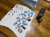
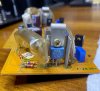
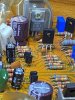
Here is a picture of my driver board and the pile of stuff that was changed on this 990.
I’m thinking something must be amis, though, as I cannot get the readings lower than 45 ma3A663517-DA7F-4508-A8B8-810B38F59A62.jpegF6A4ACAB-0192-444A-AFF9-291C3C1BBA04.jpeg
That’s why I wanted to ask if I had everything set right.
 
Well... It looks like the VD1212 had been replaced. When push comes to shove I'd be pulling the 2SC984's for inspection, hfe measurement and resistance between the junctions. Compare them to one another for reference and see if you come up with anything odd. It's not too common but they had been reported as failed on some threads around here. FWIW you may also wanna verify the differentials and take a peek at this thread about transistor pinouts on the driver amp.
 
Thanks for the replies guys!
It’s not on a DBT at the moment, but I will consider doing it that way from now on, as I have built one and have been using it regularly.
One of the reasons I built the spent fuse adapter is to eliminate the chances of shorting the fuse holders with the probes. And it gives me two free hands to adjust the trim pots.
I will read up on how to test the parts that were mentioned, but I believe they all were changed by the seller with the recap/rebuild.
Here is a picture of my driver board and the pile of stuff that was changed on this 990.
I’m thinking something must be amis, though, as I cannot get the readings lower than 45 maView attachment 2107256View attachment 2107257
That’s why I wanted to ask if I had everything set right.
Check your output transistors. You mentioned "the middle" got hot. There could be a mixed bag of outputs. The heat sink should have even temperature the whole way through.
 
I can't see what driver transistors are on there. It is possible they have the wrong substitution and could explain the BIAS current being too high. I use MJE15032G and MJE15033G in these units.
 
Check your output transistors. You mentioned "the middle" got hot. There could be a mixed bag of outputs. The heat sink should have even temperature the whole way through.
The Output Transistors look to be original.
Although I noticed the bottom code on some are different. Not sure if that’s a big deal, or if that implies they were changed.8A737860-1EAA-4B0A-BB1A-13D62F30FFE7.jpeg8C25079E-4F0E-4801-AD98-7E69DBF9BD0E.jpeg
 
Take the outer heat sink off and let's have a better look at them.
Will do.
One thing I noticed while trying to adjust the bias trim pots. The Right channel adjusted Left to Right. If I turned the screw adjuster to the Left (counter clock wise) the bias would decrease, to the Right (clockwise) the bias would increase.
But on the Left channel it was reversed. Turning counter clockwise would increase the bias and clockwise would decrease the bias.
Is this normal?
Sorry, this is all new to me :)
Thank you so much for helping me though!
Oh and the BIAS pots look to be correct.
 
I’m gonna need some thermal paste..View attachment 2107869
They appear to be original. And appears that someone was in there before. It looks like a couple of screw heads are chewed a little, and the paste is quite a mess. Normally on something this old, some dust has settled on the top sides of the surfaces. Look at each transistor for the tell-tale signs of dust. If any of them look "too clean", more than likely those have been replaced. Leave the outer heat sink off for now, it's safe to run it without it at low volume for "testing". Clean the paste off the outer heat sink and take a straight edge to it. These warp and a lot of people never notice it. It looks like the center, and center-left (as pictured) wasn't making very good physical contact with the inner heat sink. The other 3 contact areas look good. Losing that contact does result in uneven temps, and a "hot spot" because of loss of heat transfer. Under "normal" listening levels, it's no big deal. But when cranking it, the outputs in those warped area can overheat. I have seen my share of Sansui "blowouts" where the heatsinks were severely warped around the overheated/shorted outputs. In the picture where the center 3 vertical patterns are, there should have been an additional center screw to keep the sinks mated. I machine the sinks, both inner and outer, and add the screws.for maximum heat transfer. You can leave that outer perforated cage off for better air flow too.
If that thermal paste is thick and "like glue", it would be a good idea to remove each transistor to clean them, the sink, and the mica to inspect it. If the mica insulator has any cracks or flaky areas, replace them. Both Mouser and Digikey have TO-3 mica, but call them "thermal pads" when searching. Get some good thermal paste such as Dow (or DOWSIL) 340. Use it sparingly with a very thin coating. It's purpose is to only fill the imperfections in the mating surfaces. Too much and the device "floats" on the paste making for poor thermal conductivity.
But let's figure out why the BIAS is so far off first. Then worry about the "cleanup" afterwards. Check all 8 emitter resistors for consistency. They will read "almost" a short at 0.33 Ohm. But we want to see if they are all the same. Most meters won't measure them with any kind of accuracy, but consistency is what we want here to try and see why there is a "hot spot".
 
It seems that VR03 and VR04 are working to some extent and you do get close to the OEM spec for this model. I would double check the value of the trimmers [SM calls for 1.0 kohm] and check them to see if they are working as designed [linear, no dead spots, are actually close to 1.0 kohm in total resistance]. They look like new but don't overlook them as a possible issue. The Sansui SM calls out two bias settings Model "A = 50mV " [it should be 50mA =>A known and notorious Sansui typo] and "Model B => 30 mA => they got that one correct. Model A being 990/9090 and Model B being 880/8080. I use the spent fuse adapter to adjust the bias to get the probes away from the "hot" fuse clips nearby. I have found that the issue is almost always a simple one to resolve after diagnosed.
 
Sorry about the long hiatus..was waiting on Thermal compound and Mica insulators. And the woman made me paint the basement...:(.
Anyway, the thermal paste job on these was a total mess. I’ve never installed transistors with thermal paste, but I have built and worked on many computers and have used my share of thermal paste on the processors and heat sinks/fans. So I’m not totally in the dark.
Also a few of these output transistors looked to have a sort of clear caulking around them, different than the whitish paste.
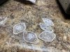
While removing them, two in the center seemed to have two mica insulators underneath them?...or maybe the mica under these two just separated?..as one was very thin.
All the transistors had some dust on the tops of them, so I’m thinking they are all original. They all test out roughly the same with a diode test. .593 - .600.
The outer heat sink does not look to be warped. A straight edge sits flat across it at all points.
The screws holding the transistors in place were, just barely snug and a few I would say we’re almost loose. It didn’t take much effort at all to free them.
Which surprised me as you stated that some of the heads were chewed up.
Now when I get this all cleaned up and start putting it back together, I’m not sure how the mica fits in with the paste. Do you put a thin layer between the transistor and the mica and another thin layer between the mica and the heat sink?
With processors, you first add some thermal paste on top then rub it off, then put on your thin layer...is this necessary with transistors and the heat sink here?


7845863A-B0F6-4777-8933-72FE99A20529.jpeg
E0CC41F3-BAB0-46F7-A203-EAC7B9014829.jpeg614C530C-6B0D-49A8-9D94-A5F7C28C2536.jpegA14AC162-3B32-443E-8A35-7D7EB2FEC2EB.jpeg
 
Do you put a thin layer between the transistor and the mica and another thin layer between the mica and the heat sink?
In a word - yes.

It might be an optical illusion but:
Two of the the mica insulators in the second picture look different - smaller? - and the holes for the transistor leads seem bigger - they actually look like TO-66 insulators - whereas what you should have is TO-3 insulators for all the transistors. :idea:
 
Last edited:
In a word - yes.

It might be an optical illusion but:
Two of the the mica insulators in the second picture look different - smaller? - and the holes for the transistor leads seem bigger - they actually look like TO-66 insulators - whereas what you should have is TO-3 insulators for all the transistors. :idea:
The screws won't line up with TO-66 mica, but I see what you mean. It definitely appears to be two different brands of mica, and confirms someone else was in there before.
 
Back
Top Bottom