

Sorry about the long hiatus..was waiting on Thermal compound and Mica insulators. And the woman made me paint the basement....
Anyway, the thermal paste job on these was a total mess. I’ve never installed transistors with thermal paste, but I have built and worked on many computers and have used my share of thermal paste on the processors and heat sinks/fans. So I’m not totally in the dark.
Also a few of these output transistors looked to have a sort of clear caulking around them, different than the whitish paste.
While removing them, two in the center seemed to have two mica insulators underneath them?...or maybe the mica under these two just separated?..as one was very thin.
All the transistors had some dust on the tops of them, so I’m thinking they are all original. They all test out roughly the same with a diode test. .593 - .600.
The outer heat sink does not look to be warped. A straight edge sits flat across it at all points.
The screws holding the transistors in place were, just barely snug and a few I would say we’re almost loose. It didn’t take much effort at all to free them.
Which surprised me as you stated that some of the heads were chewed up.
Now when I get this all cleaned up and start putting it back together, I’m not sure how the mica fits in with the paste. Do you put a thin layer between the transistor and the mica and another thin layer between the mica and the heat sink?
With processors, you first add some thermal paste on top then rub it off, then put on your thin layer...is this necessary with transistors and the heat sink here?
It's not uncommon for mica to separate especially if they have been reused, I have seen it before. Be sure there are no flakes of mica stuck on the heat sink or the transistors. It can be hard to see sometimes. Use reflections from a light if need be. The "clear" paste was the original silicone paste used on a lot of these. And it is another sign someone else was in there that failed to clean things properly, and just smeared the new paste over top the old.
Do not just willy-nilly use computer thermal paste. Many types and brands are electrically conductive so be sure to use a paste that is guaranteed to be non-conductive electrically.
Yes, you need paste on both sides of the mica. What I do, and some have their own methods, is use a cheapo artists from the "Dollar" store that is plastic, and has thicker black bristles. The black bristles are easy to see if any come loose, but I have had none come loose so far. Keep an eye out though. Spread a thin layer onto the transistor. So thin the brush strokes are easily seen right down to the metal. Place the new mica on the transistor, press it lightly in a couple spots and you'll see the brush strokes disappear as the paste spreads. You'll see what I mean. No need to press on all of them once you get the feel for how little paste is needed, except to be sure the mica sticks to the transistor and doesn't fall off. Then spread another thin layer on the mica being on the lookout for loose bristles of course, and install the transistor. Put the screws in just until they touch, then lightly snug one first, then the other. You'll start to see the paste begin to squeeze out. Then snug lightly just a little more. Move on to the rest of the transistors. When all are in like the first one, check each screw again and snug a little more if necessary. That gives the paste enough time to ooze and settle in before final snugging of the screws. Do not over tighten the screws. You'll either strip (chew) out the heads (as I pointed out before), or you'll snap a screw off. There should be split-type lock washers on the screws that keep them from coming loose. If they are missing, take a screw to the hardware store and get some that fit properly.
When installing the outer heat sink, again just use a thin layer of paste on it. You don't need paste on the inner heat sink for this. The purpose of thermal compound is only to fill in the pores/imperfections in the metal. If too much is used, the transistors/mica will "float" on the paste causing poor thermal transfer.


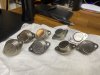
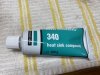
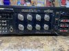
 And just the lock washers are all you needed. I have to put some on a Marantz that are missing from some previous "tech" too. All the output screws were loose. It's possible what you saw as "separated" mica, was indeed two where someone wasn't paying attention and stacked them.. Seems par for the course with (whoever it was) not cleaning the old grease off too...
 like original Sanken right down to the weight. But I couldn't tame the BIAS with them in no matter what. Swapped them out with ON Semi PNP (as a test) and BIAS dialed right in. Just a thought that if nothing else brings down the BIAS, 8 new ON Semi MJ21194G NPN output transistors might be the answer. From a reputable source that is, not from FleaBay or other shady "dealers" claiming "original NOS" or the like... Since it is obvious someone was in there before, who knows what output transistors are in there. Like