

You are using an out of date browser. It may not display this or other websites correctly.
You should upgrade or use an alternative browser.
You should upgrade or use an alternative browser.
AMC Record Player has crazy loud HUMM
- Thread starter ryan lambert
- Start date


maxhifi
Addicted Member
You need three of them. The usual method is to cut off the wires going into the cardboard can, mount a terminal strip in place of the existing cardboard can with the same number of terminals as the can has wires. Then solder the leads to the terminal strip, and also the 3 capacitors which replace the 3 sections of the old multi section capacitor.
Alternately you can buy a replacement multi section capacitor from antique electronic supply.
Alternately you can buy a replacement multi section capacitor from antique electronic supply.

Yes. I’m just confused on how I can’t put this style of cap on. And how to wire it to replaces the old cap can.
You can you radial caps. I thought that you didn't have any replacements. Just follow the schematic.
ryan lambert
New Member
So even though the colors tell me exactly what is supposed to be there, I have to hook them up in a different way now?
maxhifi
Addicted Member
So even though the colors tell me exactly what is supposed to be there, I have to hook them up in a different way now?
Well you do have to mount them in a different way, but electrically it is the same.
ryan lambert
New Member
What way would that be? Because I am kind of lost…
maxhifi
Addicted Member
What way would that be? Because I am kind of lost…
If my post above isn't descriptive enough, I suggest searching and watching videos by radiotvphononut on YouTube. He shows the method to replace can capacitors in various portable record players and radios. You may have to go through a few to find what you're looking for but I know it's in there.
ryan lambert
New Member
I have them together like that now and am having problems getting the right capacitance. I did however come across something new whenever I was looking at the schematic. If I hook up the 40mfd to the to the 33ohm 2W resistor, 80mfd to the blue and red wire and the 20mfd cap in the same spot they all read correctly but then I don’t know how it affects the circuit. How would I check that?
I have them together like that now and am having problems getting the right capacitance. I did however come across something new whenever I was looking at the schematic. If I hook up the 40mfd to the to the 33ohm 2W resistor, 80mfd to the blue and red wire and the 20mfd cap in the same spot they all read correctly but then I don’t know how it affects the circuit. How would I check that?
How are you measuring the total capacitance?
Try taking a photo of the circuit, as it currently is after your replacement of parts. A nice close-up, so the components can be clearly seen.
Something like this.
.jpg)

ryan lambert
New Member
I just threw this back together because I have soldered and unsoldered multiple time lol. But this is generally how I had it hooked up the first time and how it was labeled from the cap. I have the one 47uf going to the blue wire, 2 47uf with negatives and positives together going to the red wire, a 22uf going to the yellow, and for the sake of this picture I have the negatives of them all going to the black (common/negative). But you can also see the 82ohm 2W resistor I had to replace along with some other polypropylene capacitors.
Attachments
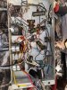
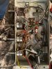
ryan lambert
New Member
I also have a terminal strip coming in the mail tomorrow to make this look neater lolI just threw this back together because I have soldered and unsoldered multiple time lol. But this is generally how I had it hooked up the first time and how it was labeled from the cap. I have the one 47uf going to the blue wire, 2 47uf with negatives and positives together going to the red wire, a 22uf going to the yellow, and for the sake of this picture I have the negatives of them all going to the black (common/negative). But you can also see the 82ohm 2W resistor I had to replace along with some other polypropylene capacitors.
I just threw this back together because I have soldered and unsoldered multiple time lol. But this is generally how I had it hooked up the first time and how it was labeled from the cap. I have the one 47uf going to the blue wire, 2 47uf with negatives and positives together going to the red wire, a 22uf going to the yellow, and for the sake of this picture I have the negatives of them all going to the black (common/negative). But you can also see the 82ohm 2W resistor I had to replace along with some other polypropylene capacitors.
We need close-up of those electrolytic caps. Try to wrap the wires, where you have the alligator clips --- so we can better see the connections.
BTW... if those clips are on the (+) connections of the caps --- they are hot. If any touch the chassis of the amp, you will have a high voltage short. The clips should have insulation on them. Even if they are temporary.
ryan lambert
New Member
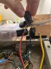
I hope this is better. I know it looks awful right now lol and yeah I’m surprised the kit I got didn’t come with those, but I haven’t used them or hooked this up to power since the first time I tried because I want to make sure I have it right next time I hook it up before I make thing permanent. Also appreciate the help big time!
Attachments
ryan lambert
New Member
Oh and the clip is holding the negative sides on the common.I hope this is better. I know it looks awful right now lol and yeah I’m surprised the kit I got didn’t come with those, but I haven’t used them or hooked this up to power since the first time I tried because I want to make sure I have it right next time I hook it up before I make thing permanent. Also appreciate the help big time!
I hope this is better. I know it looks awful right now lol and yeah I’m surprised the kit I got didn’t come with those, but I haven’t used them or hooked this up to power since the first time I tried because I want to make sure I have it right next time I hook it up before I make thing permanent. Also appreciate the help big time!
Are the cap soldered in the correct order, as in the schematic? With the correct cap going to the correct resistor?

This link may help.
https://www.valvewizard.co.uk/smoothing.html

ryan lambert
New Member
I have but like I stated I am new to the whole radio game. So you’re saying that the leads need to be cut out completely? The only positives I have soldered together are the two 47mfd to make up for the 80mfd in the multi section cap. Still any help is appreciated!
ryan lambert
New Member
I’ve been going strictly based off of the old cap cover that had the values going to certain colors. Which seems to be the same way the schematic shows.
ryan lambert
New Member
What doesn’t make much sense to me is how the 80mfd and the 40mfd positives go to the same resistor.
I have but like I stated I am new to the whole radio game. So you’re saying that the leads need to be cut out completely? The only positives I have soldered together are the two 47mfd to make up for the 80mfd in the multi section cap. Still any help is appreciated!
Try to move the caps around so their values are seen in the picture. Plus, the specific points that they are soldered to the resistors. Show these resistors (R13 and 14) that they are attached to. Need photo of R15, also.
Several photos will prolly be needed.
Thanks!
What doesn’t make much sense to me is how the 80mfd and the 40mfd positives go to the same resistor.
You really need to read that Valve Wizard article.
 The 80mfd & 40mfd caps are soldered to the two separate ends of R14. One on each side. In other words, the 82-ohm resistor is between the 80mfd and the 40mfd caps.