• The move to the new server is done. There are some software and database maintenance updates in process. This has us passing the hat around to help out. We appreciate any donations. Seriously, even a dollar helps. The payment page may be found here - https://www.audiokarma.org/support.html

And yes… another, another and another AU-717 restoration. :D

jeanpaul1812

New Member
In my previous AU-D707F Extra restoration thread, I mentioned that I planned to restore one of my two AU-717s as a gift for my brother — and I finally did it!

Here is the link for that restoration if you are interested: Sansui AU-D707F EXTRA Full Restoration

I finished the restoration in March and gave him the amplifier during the second week of April. He lives in Hoffman Estates, Illinois, and I’m in Cincinnati, so I decided to make the drive and personally deliver the precious Sansui gift.

As it turned out, that same weekend was AXPONA 2026 in Schaumburg, IL, so naturally we went and spent almost 8 hours visiting as many listening rooms as possible in one day. By the time we left, we had listened to so much music that on the drive back to his house we didn’t even turn on the radio. Lol.

The reason I bring this up is because the day before AXPONA we spent several hours listening to the newly restored AU-717 paired with his ELAC Uni-Fi 2.0 speakers. My brother was honestly blown away by how detailed, musical, and effortless the Sansui sounded. The imaging, warmth, and clarity of that amplifier reminded me once again why the AU-717 has become such a legend.

Then at AXPONA we walked into a room featuring a full Luxman setup with the flagship Luxman L-509Z driving a pair of high-end French speakers whose brand I unfortunately can’t remember. The system sounded fantastic — smooth, refined, powerful, everything you would expect from a modern reference setup.

But here’s the surprising part: the overall character and presentation honestly reminded us a lot of the restored Sansui back at home. No, I’m not saying the AU-717 was “better” or that the systems were identical, but the fact that a 1970s Sansui paired with modest ELAC speakers could give us a very similar emotional connection and listening experience compared to that Luxman setup was seriously impressive.

Now, maybe I’m a little biased toward Sansui… okay, probably very biased. :rflmao: But both my brother and I looked at each other after that demo and basically had the same reaction: “The AU-717 is hanging in there remarkably well.”

Moments like that remind me why so many of us still love these old Sansui amplifiers. There was just something special about the way Sansui voiced their gear back then. It’s honestly a shame the brand is no longer here anymore, because pieces like the AU-717 show how incredible their engineering and musicality really were.

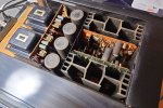
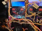
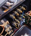
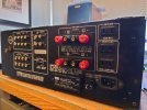
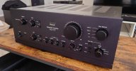
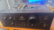
Here are some pictures of the amp in its original condition. At first, I believed this amp was completely untouched, but it turns out it had been repaired sometime back in the ‘90s. One of the driver transistors was replaced with a NTE substitute. More details to come once I get into the driver board section. :D
20260102_233256.JPG20260102_233302.JPG20260102_233305.JPG
 
Register to hide this ad
Before I start this thread, I just want to say how grateful and humbled I am by all the amazing people here on AudioKarma. Without the knowledge and generosity of this community, I would not have been able to carry out this restoration.
I’ve learned a tremendous amount by following the work of Leestereo, Hyperion, and many other talented members here. Thank you all for sharing your experience and helping keep these vintage pieces alive.

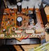
Power Supply Board

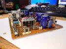
The main issue found on this board was the well-known corrosive adhesive used in older Sansui units. This glue can corrode nearby components, including ¼W resistors and diodes near the main capacitor.
As mentioned previously, one of the driver transistors had already been replaced with an NTE substitute. Coincidentally, several non-original fuses were also found, which may explain the earlier transistor failure.

20260103_000746.JPG

Work Performed

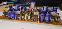
The repair process began with the complete removal of all electrolytic capacitors, followed by thorough cleaning of all adhesive residue from the PCB.
All electrolytic capacitors were replaced with low-ESR types, while smaller-value capacitors were upgraded to film types where appropriate.
All small-signal transistors were replaced with KSA992, KSC1845, and KSA945.
All diodes, including Zener diodes, were replaced.
The varistor was replaced with two 1N4148 diodes in series.
Given the age of the unit and its intended use as a gift, long-term reliability was a priority. The diodes in the bridge rectifier were upgraded to P600G-E3/54 types. The original components were carefully removed using a Dremel tool, followed by drilling, and the new diodes were then soldered directly into the bridge structure.
The four regulator transistors were replaced with MJE15032 / MJE15033 and fitted with fresh thermal compound. The heatsinks were also cleaned and polished.
All affected ¼W resistors compromised by glue contamination were replaced with metal film equivalents.
All ½W resistors were upgraded to metal film types.
All 2W resistors were replaced with wirewound types.
The relay was replaced with an Omron MY2-02-DC24.
All fuses were replaced with 7A 250VAC types.


20260302_233850.JPG20260302_235914.JPG


20260305_222322.JPG20260305_222445.JPG20260305_222402.JPG20260305_222516.JPG20260306_010347.JPG
 
Last edited:
Main filter Capacitors

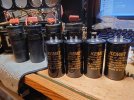
The main filter capacitors were replaced with KEMET 15,000 µF / 63V units — the same value as the original Nichicon caps.
The cross capacitors were replaced with Panasonic polypropylene types of the same value.
I would’ve also liked to try those adapter boards for mounting the main caps, but I may do that when I restore my own 717. Thank you @Kingbleu for the information. :D


20260210_194751.JPG20260210_194804.JPG20260305_223329.JPG
 
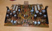
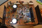
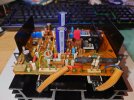
Driver Board

As I mentioned earlier in the thread, one of the driver transistors had previously been replaced with an NTE unit, and a couple of the fuses were also non-original. I believe the amp was repaired sometime in the 1990s. It apparently worked for a while afterward, but at some point the previous owner stored it away and never used it again.
Knowing that history, the first thing I checked were the output transistors — and sadly, one was shorted. At that point I knew I was about to find more issues in this area! But honestly, where’s the excitement if nothing is wrong? Lol. :jump:
Also, as usual with many Sansui amps from this era, I had to deal with the infamous corrosive glue and, in this model, a full set of fusible resistors that had drifted way out of spec.


20260103_171109.JPG20260104_132855.JPG

Work Done
  • All capacitors were replaced with low-ESR types, and the smaller value capacitors were upgraded to film types where applicable.
  • All ceramic capacitors were replaced with C0G/NP0 types.
  • All diodes and zeners were replaced.
  • All small-signal transistors were replaced with KSC1845, KSA992, TTA004B, TTC004B, and KSA945, including the bias transistor.
  • Luckily, I had two matched pairs of original NEC 2SB536 and 2SD382 driver transistors on hand, so I removed the old parts — including the NTE intruder lol — and installed the NEC transistors using new mica insulators and fresh thermal compound.
  • All 1/4W resistors affected by the glue, along with the fusible resistors, were replaced with metal film types.
  • All 1/2W resistors were also replaced with metal film types.
  • All 5W emitter resistors were replaced with wirewound types.
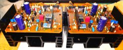
For the output transistors, I chose to replace the originals with Sankens 2SA1695 and 2SC4468. I didn’t want to go the usual route of using the Onsemi MJ21193G/MJ21194G pair because their transition frequency is around 5 MHz, which is significantly lower than the original 2SA747 and 2SC1116A outputs used in this amplifier, rated at 15 MHz.
The replacements I selected have a fT of 20 MHz, and overall their specifications are much closer to the original devices.
To mount them, instead of reusing the original sockets and bending the transistor leads, I used TO-3P adapter boards I found on eBay. They actually worked out very well. The transistors were installed with new mica pads and, of course, fresh thermal compound.
As you can see in the pictures, I also reused the original wires from the old sockets and soldered them directly to the new transistor boards to keep the installation looking as clean and factory-like as possible.


20260307_190757.JPG20260308_222406.JPG20260309_014100.JPG20260309_014201.JPG20260309_014108.JPG20260309_013825.JPG20260309_013817.JPG
 
Last edited:
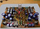
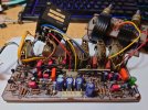
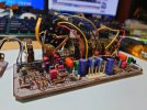
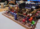
Preamp Section

20260108_021624.JPG
Parts Replaced
  • All electrolytic capacitors were replaced with low-ESR types.
  • All small-signal transistors were replaced with KSC1845 and KSA992.
  • The varistors were replaced with two 1N4148 diodes connected in series.
  • Ceramic capacitors were replaced with C0G/NP0 types.
  • Capacitors in the signal path were replaced with bipolar types where applicable.
  • Small-value capacitors were upgraded to film types.
  • All fusible resistors were replaced with metal film resistors.
  • The original film capacitors were replaced with WIMA and Panasonic polypropylene capacitors.
20260305_222025.JPG20260305_222058.JPG20260305_222115.JPG20260305_222119.JPG
 
Last edited:
Volume Pot

To properly service the volume pot, the only “difficult” part is removing the original lock star washer. I carefully cut mine using a small Dremel cutting wheel and steady hands. After that, the rest of the process is fairly straightforward.
The potentiometer must be completely disassembled so each internal section and contact board can be cleaned individually. I first cleaned everything using cotton swabs with little isopropyl alcohol, then applied DeoxIT F5 before carefully reassembling the unit.
While opening the pot, I found that the plastic bumper was broken. I replaced it with a similar piece of plastic I had on hand, shaping it into place and gently forming it with controlled heat from a candle until it fit properly.

For reassembly, I used a new M2.5 lock washer and lightly tapped it into place with a small hammer.
In my opinion, this step is absolutely worth doing. If the volume pot is not fully serviced, you can end up with uneven channel levels or intermittent balance issues.

Don’t overthink it — just do it! :D

20260311_223647.JPG20260312_201654.JPG20260311_215243.JPG20260312_211601.JPG20260312_211556.JPG20260311_211954.JPG
 
Last edited:
Beautiful work. What did you use to clean the glue. I always scrape it off and tend to leave scuff marks on the board.
 
Beautiful work. What did you use to clean the glue. I always scrape it off and tend to leave scuff marks on the board.
Oh, thank you!
I used anhydrous alcohol and let it soak into the glue for about an hour. After that, I used a small plastic scraper to lift it off. At that point it softens enough that it comes off quite easily without much force, so you avoid damaging the board or leaving scuff marks.
 
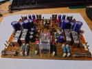
Phono Board

20260108_214911.JPG

Parts Replaced

All electrolytic capacitors were replaced with low-ESR types.
Capacitors in the signal path were replaced with film types where applicable.
Ceramic capacitors were replaced with C0G/NP0 types.
The C01 and C02 1 µF original film capacitors were replaced with polypropylene types.
All small-signal transistors were replaced with KSC1845 and KSA992.
All fusible resistors were replaced with metal film resistors.
The varistors were replaced with two 1N4148 diodes connected in series.


20260302_213801.JPG20260302_213821.JPG20260302_213835.JPG20260302_213904.JPG20260302_214009.JPG
 
Switches and Controls

I went through and thoroughly cleaned all the switches and controls in this amplifier. In my opinion, you can upgrade every electronic component with the best available parts, but if the switches are dirty, none of that really matters. Dirty contacts don’t conduct current the way they were designed to, and that can lead to all kinds of strange and intermittent issues.
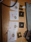
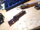
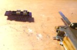
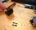
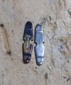
In the pictures, you can clearly see how bad the switches were. For example, on the power switch I left one side uncleaned as a direct comparison, while the other side was fully cleaned.
Also, regarding the RCA connectors, I only polished one in the comparison photo to show the difference against the oxidized originals. In a separate photo, you can see all of the RCA connectors fully polished and restored.
In one of the images, you can also see that I replaced the electrolytic capacitors on the pre-power amp switch board with Panasonic polypropylene types. The switch itself was also fully cleaned and serviced.


20260111_210329.JPG20260111_212134.JPG20260112_002820.JPG20260112_004519.JPG20260113_000744.JPG20260113_001340.JPG20260113_223427.JPG20260113_235040.JPG20260115_200104.JPG20260208_210142.JPG
 
Last edited:
Speaker Terminals and IEC Inlet

For this amplifier, I initially considered doing a DIY speaker terminal upgrade using hard black plastic and binding posts, as I’ve done on my D11II, 719, and D707F Extra. However, that plan didn’t work out as expected. The original speaker terminal assembly on the 717 doesn’t use screws to secure it to the rear panel — instead it relies on molded plastic tabs, which would have made a custom solution difficult without 3D printing.

In the end, I sourced a set of brass speaker terminals with a 3D-printed enclosure from eBay.
Installing the new terminals was straightforward. To connect the wiring, I crimped brass ring terminals onto the wire ends and secured them to the posts for a solid connection.
One thing I chose not to use was the supplied steel nuts. I prefer to avoid steel in the signal path where possible, so I replaced them with brass nuts instead.
Finally, I also added an IEC inlet to allow the use of a proper detachable power cable.

20260401_223931.JPG20260402_003833.JPG20260402_003842.JPG
 
Conclusions

To be completely honest, this restored 717 sounds, in my opinion, a little better than my restored 719, and is actually closer in character to my D707F Extra.
I believe the main difference with the 719 comes down to the preamp design and the power supply, which feels a bit less robust compared to the 717’s more dual-mono-style layout. That said, the 719 does have a superior phono stage — its diamond differential design in the driver stage is, at least on paper, more refined than the one in the 717.
It also feels like Sansui scaled things back slightly with the 719 compared to the 717. The 717 has a black-painted chassis, internal shielding, and generally more substantial controls and hardware. The 717 uses solid aluminum knobs secured with hex set screws, while the 719 uses a more plastic-core design. Also Sansui took away the Pre-amp switch on that amp!

Overall, I can understand why many people prefer the 717 over the 719.
On a personal note, this experience also reminded me of hearing that Luxman at AXPONA — I could close my eyes and easily imagine I was listening to the 717. That amplifier really is something special.

Finally, I’m happy that my brother will get to enjoy this restored Sansui amplifier.


20260401_223921.JPG20260402_003907.JPG20260404_112356.JPG20260402_003921.JPG20260412_113656.JPG20260412_113649.JPG20260412_113715.JPG
 
Last edited:
Switches and Controls

I went through and thoroughly cleaned all the switches and controls in this amplifier. In my opinion, you can upgrade every electronic component with the best available parts, but if the switches are dirty, none of that really matters. Dirty contacts don’t conduct current the way they were designed to, and that can lead to all kinds of strange and intermittent issues.
In the pictures, you can clearly see how bad the switches were. For example, on the power switch I left one side uncleaned as a direct comparison, while the other side was fully cleaned.
Also, regarding the RCA connectors, I only polished one in the comparison photo to show the difference against the oxidized originals. In a separate photo, you can see all of the RCA connectors fully polished and restored.
In one of the images, you can also see that I replaced the electrolytic capacitors on the pre-power amp switch board with Panasonic polypropylene types. The switch itself was also fully cleaned and serviced.


View attachment 3763263View attachment 3763264View attachment 3763265View attachment 3763266View attachment 3763267View attachment 3763268View attachment 3763269View attachment 3763270View attachment 3763271View attachment 3763289
Very nice work. I use Kemet 5.6uF x50v film cap on that pre-main board. That switch is an Ahills foot of this amp (and also 517 little brother). Unfortunately cleaning it alleviates the issue only for a while and it tends to comeback. I saw similar switch at DigiKey by the company called E-switch however their version is phisically smaller I was thinking about recreating the whole board to use that switch or use llatching relay and button. I do not know but there are several optiopn and another is to create a small adapter to match smaller footprint of that E-Switch
 
Last edited:
Back
Top Bottom