daylite
Active Member
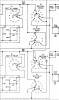
I was facing a job involving rewiring of the 500C’s 7-position 5-section selector switch and realized I did not have near the understanding I needed to feel good starting. To help myself get there I put together 7 drawings to show the state of the network and signal path for each switch position. I’m sharing them here.
The drawings show the signal path highlighted in blue and at the same time illustrate what nets are grounded in the various states. Grounded nets are highlighted in red, though in some cases I didn’t highlight a grounded net because it was an obvious dead end, or it just didn’t look relevant to the main function selected.
I have attached the drawings to this post. The drawings also make a nice animation shown here. It’s set to go pretty fast. Nevertheless, I found it instructive when watched for several cycles while focusing on subregions. If you download the animation and open it in a program that does not play it automatically you can step through at your own pace. You can also click on the gif in the attachment area to step through it. -d [EDIT: DG explains below that the source schematic from Fisher is wrong around Section 3, The frame files and animation here have all been updated with the correction he recommended. New files have 'Corrected-Section-3' in the filenames. -d ........Dec 24, 2021 9:22 AM ]

The drawings show the signal path highlighted in blue and at the same time illustrate what nets are grounded in the various states. Grounded nets are highlighted in red, though in some cases I didn’t highlight a grounded net because it was an obvious dead end, or it just didn’t look relevant to the main function selected.
I have attached the drawings to this post. The drawings also make a nice animation shown here. It’s set to go pretty fast. Nevertheless, I found it instructive when watched for several cycles while focusing on subregions. If you download the animation and open it in a program that does not play it automatically you can step through at your own pace. You can also click on the gif in the attachment area to step through it. -d [EDIT: DG explains below that the source schematic from Fisher is wrong around Section 3, The frame files and animation here have all been updated with the correction he recommended. New files have 'Corrected-Section-3' in the filenames. -d ........Dec 24, 2021 9:22 AM ]
Attachments
-
 Switch POSITION 1 v2 Corrected Section 3.png482 KB · Views: 43
 -
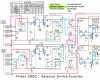 Switch POSITION 2 v2 Corrected Section 3.png488.9 KB · Views: 41
 -
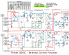 Switch POSITION 3 v2 Corrected Section 3.png487.9 KB · Views: 37
 -
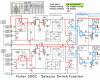 Switch POSITION 4 v2 Corrected Section 3.png488.9 KB · Views: 36
 -
 Switch POSITION 5 v2 Corrected Section 3.png489.1 KB · Views: 36
 -
 Switch POSITION 6 v2 Corrected Section 3.png488.7 KB · Views: 34
 -
 Switch POSITION 7 v2 Corrected Section 3.png490.2 KB · Views: 36
 -
 _Framed-Corrected-S3-Fisher-500C---7-Paths-STR.gif111 KB · Views: 32
Last edited: