Sorry for another Wattage question -- For the Heaters -- I see a 220 ohm requirement -- Looking at the wire size - I am thinking a Larger WATT value may be required - higher than the 1/4 or 1/2 standard --- is that correct ?100 ohm screen resistors you're talking about? Only particular reason to not go really low watt parts is the voltage rating. These won't be dropping much of anything so it doesn't so much apply, but generally the physically smaller the resistor, the less voltage you can drop across them. The bigger 1/2 watt types are usually 350v, but the small ones are 200 or 250. It goes up or down from there depending on the resistor in question.
for bleeders in a power supply you might want 1 or 2W parts even if they don't dissipate anywhere near that, simply for the voltage rating.


You are using an out of date browser. It may not display this or other websites correctly.
You should upgrade or use an alternative browser.
You should upgrade or use an alternative browser.
ANOTHER - Impulse buy -- Magnavox 8802
- Thread starter S Swanson
- Start date

DirtyErnie
Well-Known Member
220 ohm on 6.3v? = 28.6ma, 180.4mw. 1/2 watt would give you a 2.5x margin.
Absent real data ----- I guess ---MY default is -- A question -what is the consensus ?- (opinions Welcome )- Preferably the --experience ---of others --- Who Know,-- and have a good reputation.Old transformers can be a great value, not all old iron is good but plenty is. I know nothing specifically about Eico 40 transformers but I have a hard time believing they aren't at least decent. You'll be making roughly half the power that these were originally paired with, so that also tends to improve performance.
Glowing reports - say something - but i would rather have REAL numbers ---
OK thank you --- I really need to get OHM's law under my belt ---220 ohm on 6.3v? = 28.6ma, 180.4mw. 1/2 watt would give you a 2.5x margin.
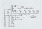

What numbers would make you feel better?
So, I'm having trouble keeping up with the various flipping and flopping you tend to do @S Swanson - exactly WHAT iron are you intending to use on this 8800? Eico ST-40 or ST-70 or other?
The Eico ST-40 iron would be a better fit here- the ST-40 was cathode biased, so those transformers are ~8K plate to plate impedance, which is a good match for the 6V6GT. You would be running these (As @gadget73 indicated) at half their rated power, so by "taking it easy" the transformers would be in a much sweeter spot performance wise. These are good classic iron. I would expect =spectacular= results.
The ST-70 used fixed bias, so the plate to plate impedance on those are more like 6.6K, probably a better fit for a 6L6 type tube.
OK To me it seems a bit confusing - what would this connection look like in the real world - Is this connection in ADDITION to the green and green yellow ? -- And I am assuming they (6v6s ) all get a connection --- Daisy chain ? style ? --- As I said kinda confused

OK--- Was I was unclear ? The question about the ST 70 transformers was ABOUT A FUTURE Project (see post 170 ) and has nothing to do with the 8802 -What numbers would make you feel better?
So, I'm having trouble keeping up with the various flipping and flopping you tend to do @S Swanson - exactly WHAT iron are you intending to use on this 8800? Eico ST-40 or ST-70 or other?
The Eico ST-40 iron would be a better fit here- the ST-40 was cathode biased, so those transformers are ~8K plate to plate impedance, which is a good match for the 6V6GT. You would be running these (As @gadget73 indicated) at half their rated power, so by "taking it easy" the transformers would be in a much sweeter spot performance wise. These are good classic iron. I would expect =spectacular= results.
The ST-70 used fixed bias, so the plate to plate impedance on those are more like 6.6K, probably a better fit for a 6L6 type tube.
I made A choice (see post 178 and 179 ) So yes The Plan is to use the Eico st40 Iron - -- BTW - pretty sure the ST70 iron would not fit the chassis - BUT again That was Not ON THE TABLE--- as a option - and never was -- I probably should have started another Thread about those transformers (A compatibility question )-- as recommended - per Gadget's recommendation -- --( see-- I think post 175 )
In any case - If i seemed to Flip flop on the transformers - that was PERHAPS of NOT KNOWING what was the wise choice . FULL Circle -- as i said - If i am testing everyone's patients I apologize - and A quick note; Sometimes my writing can seem way More Strident --than Intended.
Perhaps a happy face emoji would help?
No worries, no patience tested, just sometimes have trouble following the design as it evolves as several options were discussed. Just want to be helpful so I have to keep track of what you're building. I think you will be tickled pink with the ST-40 iron.
As to the virtual center- it's not even really that important. Please do not connect the 6V6 cathodes together. That virtual center point between the two 220 ohm resistors just connects to =any one= 6V6 cathode, just to hold the filament supply up above ground. As @gadget73 mentioned, since any one 6V6 socket has all of the required connect points, it's easiest to install these resistors on just one 6V6 socket, from one side of the filament to cathode, and other side of filament to cathode. like this:
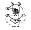
As to the virtual center- it's not even really that important. Please do not connect the 6V6 cathodes together. That virtual center point between the two 220 ohm resistors just connects to =any one= 6V6 cathode, just to hold the filament supply up above ground. As @gadget73 mentioned, since any one 6V6 socket has all of the required connect points, it's easiest to install these resistors on just one 6V6 socket, from one side of the filament to cathode, and other side of filament to cathode. like this:
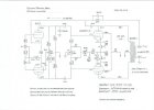
Started Moving agin on theI have taken the time to compose a new proposed schematic for your 8802 rebuild, that includes the adjustable bias, DC balance, but removes the AC balance from the front end. The feedback compensation capacitor will need to be dialed in for your exact output transformer using the scope, dummy load and signal generator with my assistance. I do not have color codes indicated for the output transformer- I can propose some when I know what transformer you are using for sure. If it is the stock iron it will be as indicated on Dave's schematic, and I will add it here. Please look it over and ask any questions that come to mind. The power supply below is exactly the same.
View attachment 3801294
View attachment 3801295
I have taken the time to compose a new proposed schematic for your 8802 rebuild, that includes the adjustable bias, DC balance, but removes the AC balance from the front end. The feedback compensation capacitor will need to be dialed in for your exact output transformer using the scope, dummy load and signal generator with my assistance. I do not have color codes indicated for the output transformer- I can propose some when I know what transformer you are using for sure. If it is the stock iron it will be as indicated on Dave's schematic, and I will add it here. Please look it over and ask any questions that come to mind. The power supply below is exactly the same.
View attachment 3801294
View attachment 3801295
Moving forward on the project -- And getting to the place where i need to integrate the Pots (50 ohm )I have taken the time to compose a new proposed schematic for your 8802 rebuild, that includes the adjustable bias, DC balance, but removes the AC balance from the front end. The feedback compensation capacitor will need to be dialed in for your exact output transformer using the scope, dummy load and signal generator with my assistance. I do not have color codes indicated for the output transformer- I can propose some when I know what transformer you are using for sure. If it is the stock iron it will be as indicated on Dave's schematic, and I will add it here. Please look it over and ask any questions that come to mind. The power supply below is exactly the same.
View attachment 3801294
View attachment 3801295
into the circuit -
I have taken the time to compose a new proposed schematic for your 8802 rebuild, that includes the adjustable bias, DC balance, but removes the AC balance from the front end. The feedback compensation capacitor will need to be dialed in for your exact output transformer using the scope, dummy load and signal generator with my assistance. I do not have color codes indicated for the output transformer- I can propose some when I know what transformer you are using for sure. If it is the stock iron it will be as indicated on Dave's schematic, and I will add it here. Please look it over and ask any questions that come to mind. The power supply below is exactly the same.
View attachment 3801294
View attachment 3801295
Will be wiring as drawn - and hope for the best --- Seems like I may need a bit of explanation - About what is going on here --- As a example I dont see how to adjust ck and dk --- without adjusting _ a new value from k to t
(Schematic again below.) The cathode current (bias current) from tube C flows through it's 10 ohm cathode resistor to point K, causing a small voltage drop from Ck to K. The similar cathode current from tube D flows through it's 10 ohm resistor to point K, causing a small voltage drop from Dk to K. First, understand that if the bias current from C and from D are exactly equal (meaning bias currents are balanced), the voltage dropped across each 10 ohm resistor will be equal but opposite, so a voltage measurement from Ck to Dk will equal 0V, because they are opposite polarity, therefore cancel.
At point K the two bias currents join, and flow from point K to point T. In doing so, it drops a voltage across the 150 ohm resistor, so that from a measurement of voltage between points T and K we can compute the SUM of the two bias currents. We will adjust the BIAS adj pot until the SUM of the two currents equals 2 times the current we want from each tube.

In order for the combined bias current to continue flowing from point T to the ground, which is the center wiper of the Balance pot, the current must flow through the 50 ohm BIAS adjustment pot, then divide more or less equally, to flow through both the upper 47 ohm and lower 47 ohm resistors, and through either side of the balance pot to make it to the center wiper and to ground. (This bias current cannot flow through the 470K grid return resistors, so it has to go to ground.) The two currents flowing through these two halves of the DC BAL pot each generate a small voltage drop to ground. This small voltage drop on either side of the BAL pot wiper appears between the 470K grid return resistor and ground for each output tube, so the BAL pot is really adjusting their grid voltages. Depending upon where the center wiper of the BAL pot is positioned, we can "teeter totter" a small voltage to raise or lower the DC grid voltage of tubes C and D.
If tubes C and D were perfectly matched and identical, the bias current of each would be equal with the BAL pot exactly centered so both grids would be at the exact same DC voltage. However, let's say tube C is weaker, so the bias current for that side is smaller, and tube D is stronger so the current on that side is greater. If we move the BAL pot wiper closer to the "D" side, the grid for tube C will be increased, turning the tube C on more, and the grid for tube D will be decreased, turning that tube down slightly. The adjustment range is not huge here- C and D should be somewhat reasonably matched, or the BAL pot will have to be moved all the way to one side, and the currents still may not balance equally. If C and D are reasonably close, the BAL can achieve equal currents (such that voltage betweek Ck and Dk = 0) somewhere within it's adjustment range.
Setting bias current is a two step operation. Generally you will first power on with the BIAS pot set for maximum resistance (lowest current), and the BAL pot set to the center position. As the amp warms up, you will then first adjust the BIAS pot to bring the SUM of the currents up towards but a little bit short of the final goal, then, you will measure the voltage between Ck and Dk, and adjust the BAL pot to bring it to zero. Then you will measure from T to K and adjust the BIAS pot again closer to the goal, then BAL, back and forth until the tubes are balanced, and at the desired bias current. You will find that one control will have some effect on the other, so you will have to play round robin until everything is set. As the amp continues to warm up, and the line voltage changes, you will see both BIAS and BAL voltage measurement vary and drift around. The key is not perfect aerospace precision, but to keep it all in the ball-park as the amp is operated.
Did I make that clear as mud?
At point K the two bias currents join, and flow from point K to point T. In doing so, it drops a voltage across the 150 ohm resistor, so that from a measurement of voltage between points T and K we can compute the SUM of the two bias currents. We will adjust the BIAS adj pot until the SUM of the two currents equals 2 times the current we want from each tube.
In order for the combined bias current to continue flowing from point T to the ground, which is the center wiper of the Balance pot, the current must flow through the 50 ohm BIAS adjustment pot, then divide more or less equally, to flow through both the upper 47 ohm and lower 47 ohm resistors, and through either side of the balance pot to make it to the center wiper and to ground. (This bias current cannot flow through the 470K grid return resistors, so it has to go to ground.) The two currents flowing through these two halves of the DC BAL pot each generate a small voltage drop to ground. This small voltage drop on either side of the BAL pot wiper appears between the 470K grid return resistor and ground for each output tube, so the BAL pot is really adjusting their grid voltages. Depending upon where the center wiper of the BAL pot is positioned, we can "teeter totter" a small voltage to raise or lower the DC grid voltage of tubes C and D.
If tubes C and D were perfectly matched and identical, the bias current of each would be equal with the BAL pot exactly centered so both grids would be at the exact same DC voltage. However, let's say tube C is weaker, so the bias current for that side is smaller, and tube D is stronger so the current on that side is greater. If we move the BAL pot wiper closer to the "D" side, the grid for tube C will be increased, turning the tube C on more, and the grid for tube D will be decreased, turning that tube down slightly. The adjustment range is not huge here- C and D should be somewhat reasonably matched, or the BAL pot will have to be moved all the way to one side, and the currents still may not balance equally. If C and D are reasonably close, the BAL can achieve equal currents (such that voltage betweek Ck and Dk = 0) somewhere within it's adjustment range.
Setting bias current is a two step operation. Generally you will first power on with the BIAS pot set for maximum resistance (lowest current), and the BAL pot set to the center position. As the amp warms up, you will then first adjust the BIAS pot to bring the SUM of the currents up towards but a little bit short of the final goal, then, you will measure the voltage between Ck and Dk, and adjust the BAL pot to bring it to zero. Then you will measure from T to K and adjust the BIAS pot again closer to the goal, then BAL, back and forth until the tubes are balanced, and at the desired bias current. You will find that one control will have some effect on the other, so you will have to play round robin until everything is set. As the amp continues to warm up, and the line voltage changes, you will see both BIAS and BAL voltage measurement vary and drift around. The key is not perfect aerospace precision, but to keep it all in the ball-park as the amp is operated.
Did I make that clear as mud?
Last edited:
(Schematic again below.) The cathode current (bias current) from tube C flows through it's 10 ohm cathode resistor to point K, causing a small voltage drop from Ck to K. The similar cathode current from tube D flows through it's 10 ohm resistor to point K, causing a small voltage drop from Dk to K. First, understand that if the bias current from C and from D are exactly equal (meaning bias currents are balanced), the voltage dropped across each 10 ohm resistor will be equal but opposite, so a voltage measurement from Ck to Dk will equal 0V, because they are opposite polarity, therefore cancel.
At point K the two bias currents join, and flow from point K to point T. In doing so, it drops a voltage across the 150 ohm resistor, so that from a measurement of voltage between points T and K we can compute the SUM of the two bias currents. We will adjust the BIAS adj pot until the SUM of the two currents equals 2 times the current we want from each tube.
View attachment 3841921
In order for the combined bias current to continue flowing from point T to the ground, which is the center wiper of the Balance pot, the current must flow through the 50 ohm BIAS adjustment pot, then divide more or less equally, to flow through both the upper 47 ohm and lower 47 ohm resistors, and through either side of the balance pot to make it to the center wiper and to ground. (This bias current cannot flow through the 470K grid return resistors, so it has to go to ground.) The two currents flowing through these two halves of the DC BAL pot each generate a small voltage drop to ground. This small voltage drop on either side of the BAL pot wiper appears between the 470K grid return resistor and ground for each output tube. Depending upon where the center wiper of the BAL pot is positioned, we can "teeter totter" a small voltage to raise or lower the DC grid voltage of tubes C and D. If tubes C and D were perfectly matched and identical, the bias current of each would be equal with the BAL pot exactly centered so both grids would be at the exact same DC voltage. However, let's say tube C is weaker, so the bias current for that side is smaller, and tube D is stronger so the current on that side is greater. If we move the BAL pot wiper closer to the "D" side, the grid for tube C will be higher, turning the tube on more, and the grid for tube D will be lower, turning that tube down slightly. The adjustment range is not huge here- C and D should be somewhat reasonably matched, or the BAL pot will have to be moved all the way to one side, and the currents still may not balance equally. If C and D are reasonably close, the BAL can achieve equal currents (such that voltage betweek Ck and Dk = 0) somewhere within it's adjustment range.
Setting bias current is a two step operation. Generally you will first power on with the BIAS pot set for maximum resistance (lowest current), and the BAL pot set to the center position. As the amp warms up, you will then first adjust the BIAS pot to bring the SUM of the currents up towards but a little bit short of the final goal, then, you will measure the voltage between Ck and Dk, and adjust the BAL pot to bring it to zero. Then you will measure from T to K and adjust the BIAS pot again closer to the goal, then BAL, back and forth until the tubes are balanced, and at the desired bias current. You will find that one control will have some effect on the other, so you will have to play round robin until everything is set. As the amp continues to warm up, and the line voltage changes, you will see both BIAS and BAL voltage measurement vary and drift around. The key is not perfect aerospace precision, but to keep it all in the ball-park as the amp is operated.
Did I make that clear as mud?
Actually This is VERY helpful - enlightening even - As you probably imagined - Knowing my current level of expertise ! ( note to self ---humble yourself it;s appropriate )(Schematic again below.) The cathode current (bias current) from tube C flows through it's 10 ohm cathode resistor to point K, causing a small voltage drop from Ck to K. The similar cathode current from tube D flows through it's 10 ohm resistor to point K, causing a small voltage drop from Dk to K. First, understand that if the bias current from C and from D are exactly equal (meaning bias currents are balanced), the voltage dropped across each 10 ohm resistor will be equal but opposite, so a voltage measurement from Ck to Dk will equal 0V, because they are opposite polarity, therefore cancel.
At point K the two bias currents join, and flow from point K to point T. In doing so, it drops a voltage across the 150 ohm resistor, so that from a measurement of voltage between points T and K we can compute the SUM of the two bias currents. We will adjust the BIAS adj pot until the SUM of the two currents equals 2 times the current we want from each tube.
View attachment 3841921
In order for the combined bias current to continue flowing from point T to the ground, which is the center wiper of the Balance pot, the current must flow through the 50 ohm BIAS adjustment pot, then divide more or less equally, to flow through both the upper 47 ohm and lower 47 ohm resistors, and through either side of the balance pot to make it to the center wiper and to ground. (This bias current cannot flow through the 470K grid return resistors, so it has to go to ground.) The two currents flowing through these two halves of the DC BAL pot each generate a small voltage drop to ground. This small voltage drop on either side of the BAL pot wiper appears between the 470K grid return resistor and ground for each output tube. Depending upon where the center wiper of the BAL pot is positioned, we can "teeter totter" a small voltage to raise or lower the DC grid voltage of tubes C and D. If tubes C and D were perfectly matched and identical, the bias current of each would be equal with the BAL pot exactly centered so both grids would be at the exact same DC voltage. However, let's say tube C is weaker, so the bias current for that side is smaller, and tube D is stronger so the current on that side is greater. If we move the BAL pot wiper closer to the "D" side, the grid for tube C will be higher, turning the tube on more, and the grid for tube D will be lower, turning that tube down slightly. The adjustment range is not huge here- C and D should be somewhat reasonably matched, or the BAL pot will have to be moved all the way to one side, and the currents still may not balance equally. If C and D are reasonably close, the BAL can achieve equal currents (such that voltage betweek Ck and Dk = 0) somewhere within it's adjustment range.
Setting bias current is a two step operation. Generally you will first power on with the BIAS pot set for maximum resistance (lowest current), and the BAL pot set to the center position. As the amp warms up, you will then first adjust the BIAS pot to bring the SUM of the currents up towards but a little bit short of the final goal, then, you will measure the voltage between Ck and Dk, and adjust the BAL pot to bring it to zero. Then you will measure from T to K and adjust the BIAS pot again closer to the goal, then BAL, back and forth until the tubes are balanced, and at the desired bias current. You will find that one control will have some effect on the other, so you will have to play round robin until everything is set. As the amp continues to warm up, and the line voltage changes, you will see both BIAS and BAL voltage measurement vary and drift around. The key is not perfect aerospace precision, but to keep it all in the ball-park as the amp is operated.
Did I make that clear as mud?
OK, @S Swanson - you have indicated to me in your PM that you are considering doing a power-on test using the original transformers.
The polarity of the stock output transformers (brown versus blue) will be correct as built (as long as nothing got majorly crossed). When you eventually install your new transformers we'll need to do some testing with your dummy load, scope, and signal generator to confirm the correct polarity, and I can help you through that. For now, though, you are good to go on the polarity front.
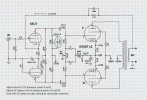
I do have concern that this recipe I gave you may need a minor tweak to work with the stock transformers- namely, the 100pF "optional" cap that I show circled in the dotted line below. In Dave's first version of the build (his schematic attached below), this capacitor was a 270pF to GND. (The far end of that cap can be tied either to GND as he shows, or tied across the resistor as I show, it does not matter, both are an "AC ground".) The stock transformers have more resonant tendency than better transformers, so the 270pF was there as a frequency limiter, to ensure the amp was stable. I dropped this value to 100pF assuming a much better transformer, which still needs to be tested and proven, but should work fine. I suggest you consider installing this 100pF cap, or a 270pF cap, (or parallel two 100pF caps to make 200pF) to ensure the amp is stable for your initial test.
This is where that dummy load and scope are handy- I never power on an amp for the first time unless I have the output loaded with rated resistive dummy load (never speaker!) and have a scope watching the output at the load to make sure I am not oscillating. Oscillation will usually be at frequencies above audible, and you need the scope to determine if it's happening. If you connect an amp that is oscillating to speakers, you will quickly burn out the tweeters and possibly do other damage, so it's important to check for.
The polarity of the stock output transformers (brown versus blue) will be correct as built (as long as nothing got majorly crossed). When you eventually install your new transformers we'll need to do some testing with your dummy load, scope, and signal generator to confirm the correct polarity, and I can help you through that. For now, though, you are good to go on the polarity front.
I do have concern that this recipe I gave you may need a minor tweak to work with the stock transformers- namely, the 100pF "optional" cap that I show circled in the dotted line below. In Dave's first version of the build (his schematic attached below), this capacitor was a 270pF to GND. (The far end of that cap can be tied either to GND as he shows, or tied across the resistor as I show, it does not matter, both are an "AC ground".) The stock transformers have more resonant tendency than better transformers, so the 270pF was there as a frequency limiter, to ensure the amp was stable. I dropped this value to 100pF assuming a much better transformer, which still needs to be tested and proven, but should work fine. I suggest you consider installing this 100pF cap, or a 270pF cap, (or parallel two 100pF caps to make 200pF) to ensure the amp is stable for your initial test.
This is where that dummy load and scope are handy- I never power on an amp for the first time unless I have the output loaded with rated resistive dummy load (never speaker!) and have a scope watching the output at the load to make sure I am not oscillating. Oscillation will usually be at frequencies above audible, and you need the scope to determine if it's happening. If you connect an amp that is oscillating to speakers, you will quickly burn out the tweeters and possibly do other damage, so it's important to check for.
Attachments
I Ordered 1 set of the BNC connectors - and 2 of the Splitters -- LATE I know - Procrastination is easy --I strongly suggest building a dummy load, and picking up a signal generator. (Don't use the one built into the scope if it has one.) You will need these to build this amp correctly, tune the feedback, and verify it is stable. Part of the cost of making your own path away from pre-designed complete recipes is that you have to do more validation for yourself, and it can't be guessed at. It's time to take these steps, there is a lot of help, so no worries.
Testing of the amplifier requires a dummy load for the rated load, as measurements provided with an open load are not valid, and you don't want to be subjecting speakers to maximum output power. I have a diagram below for one channel of a simple 4 and 8 ohm load that allows you to switch the load open for those tests that require it. This will obviously support both 4 and 8 ohm amplifiers. Works great as-is for the types of lower power amplifiers you have built so far. If you get into the really big boys, limit test time to a few minutes, or add a heatsink and fan if you get really crazy.
Suggestions for the parts:
A nice smaller heavy aluminum box that will conduct heat nicely
Four 4 ohm 100 watt power resistors (need not be dual flange, but that is nice)
Two heavy ON-OFF-ON switches (available at Home Depot here)
Two 5-way speaker banana jack binding posts of your choice
Two RCA input connectors (for signal out to scope)
Basic RCA male to male interconnect cables
BNC to RCA adapters (greatly simplifies connectivity)
Two RCA female to dual RCA splitter cables
Build the load with two channels- many tests require you to drive and load both channels simultaneously. Don't skip the 4 ohm - open - 8 ohm functionality. (open is center switch position.) You will need to be able to switch the load open (with signal still going to scope) for stability testing. Use a heavy lamp cord for the wiring between the speaker terminals and the switch and resistors, wire to the RCA connector can be lighter, need not be shielded.
View attachment 3826235
I have reached the point of connecting the Balance pot -- and the Bias Pot - This may seem basic but it looks like Wiper - is pointing to the right - I am assuming to indicate A Rising resistance -- ?? Just - In favor of an abundance of caution -- giggles welcomeOK, @S Swanson - you have indicated to me in your PM that you are considering doing a power-on test using the original transformers.
The polarity of the stock output transformers (brown versus blue) will be correct as built (as long as nothing got majorly crossed). When you eventually install your new transformers we'll need to do some testing with your dummy load, scope, and signal generator to confirm the correct polarity, and I can help you through that. For now, though, you are good to go on the polarity front.
I do have concern that this recipe I gave you may need a minor tweak to work with the stock transformers- namely, the 100pF "optional" cap that I show circled in the dotted line below. In Dave's first version of the build (his schematic attached below), this capacitor was a 270pF to GND. (The far end of that cap can be tied either to GND as he shows, or tied across the resistor as I show, it does not matter, both are an "AC ground".) The stock transformers have more resonant tendency than better transformers, so the 270pF was there as a frequency limiter, to ensure the amp was stable. I dropped this value to 100pF assuming a much better transformer, which still needs to be tested and proven, but should work fine. I suggest you consider installing this 100pF cap, or a 270pF cap, (or parallel two 100pF caps to make 200pF) to ensure the amp is stable for your initial test.
This is where that dummy load and scope are handy- I never power on an amp for the first time unless I have the output loaded with rated resistive dummy load (never speaker!) and have a scope watching the output at the load to make sure I am not oscillating. Oscillation will usually be at frequencies above audible, and you need the scope to determine if it's happening. If you connect an amp that is oscillating to speakers, you will quickly burn out the tweeters and possibly do other damage, so it's important to check for.
View attachment 3846101

I assume you refer to the bias pot. That's just a convention for a potentiometer symbol. I would measure it each way from the wiper and install it such that clockwise rotation increase bias current just for the sake of intuition.
This is how I would draw it and install it. This way if the wiper ever fails to an open condition the bias will go to minimum since the circuit will see the max resistance of the pot in the cathode string. Set it so that CW rotation decreases the resistance which will increase current.

This is how I would draw it and install it. This way if the wiper ever fails to an open condition the bias will go to minimum since the circuit will see the max resistance of the pot in the cathode string. Set it so that CW rotation decreases the resistance which will increase current.
The symbol is just meant to indicate a variable resistance, there is no deeper meaning as to which direction is which.
For the balance pot, it does not really matter much- you will dial it until the voltage between Ck and Dk is zero volts, so there is no defined up or down direction.
Yes. That. Nice to see bias current increase when you turn it clockwise.Set it so that CW rotation decreases the resistance which will increase current.
For the balance pot, it does not really matter much- you will dial it until the voltage between Ck and Dk is zero volts, so there is no defined up or down direction.
Thank you -- BTW no Duct tape will not fix everything -- and what if your other half, finds you neither hansom or handy ?I assume you refer to the bias pot. That's just a convention for a potentiometer symbol. I would measure it each way from the wiper and install it such that clockwise rotation increase bias current just for the sake of intuition.
This is how I would draw it and install it. This way if the wiper ever fails to an open condition the bias will go to minimum since the circuit will see the max resistance of the pot in the cathode string. Set it so that CW rotation decreases the resistance which will increase current.
View attachment 3846243