I wish I could take credit for the work in the photo - thats DAVE's Gs original mod on the 8800 - .What I was showing - aside from the nice work was, the complexity ( of the components )over the tube - and it got me wondering if all that could be - without adverse affect be simplified by using a tag strip -- I understand some elements are better placed as close to the tube as practical How close ? - and are there KEY items ? i should prioritize ? WonderingWell, I will say it looks like your soldering is getting better. Those components are really tight in that picture you posted. As long as nothing is touching and shorting, it should be OK- but keep in mind, when you cramp stuff in there so tightly it becomes a real challenge to change anything afterwards. The decision of whether, where, and how big of a terminal strip you should place is part of the artform that is amp building- and also why when you were whingeing about how to build your 8600 I strongly advised doing sketches on paper to work out where everything will connect- you can go component by component and in the end paint yourself into a corner. The sketch lets you work out every connection ahead of time and iterate quickly on the best arrangement to make it quick and easy to build, and relatively easy to service later. It looks like you are doing pretty good though.
Yes, there are some minor component differences between Dave's schematic and what I have drawn for you. I'm not going to dive into Dave's under-chassis build photos to figure out what differences you are mentioning- are there any you would like to call out?
Yes, the above schematic (now disappeared from above as it is outdated, and appearing here now) is the one you are building to.
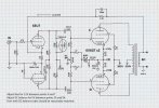
Not to frustrate you, but I have made one additional (*Optional) modification. The 100pF capacitor across the 220K resistor (that is circled with a dashed line) is extra insurance. I don't remember whether you have an oscilloscope, signal generator, or dummy load, and you are setting about the somewhat risky venture of building and amplifier with perhaps not the equipment to properly verify feedback compensation or stability tuning. The 100pF capacitor was used in the original design as a "safety margin" to make sure the amplifier was stable under different conditions. Also, the feedback cap (the one at the top center, that was labelled "TBD" is now 750pF. This was the correct value for both versions of Dave's 8800 redesign, and is a fair guess for what you will need with your new transformers. Please let me know if you have questions/concerns.
View attachment 3823830


You are using an out of date browser. It may not display this or other websites correctly.
You should upgrade or use an alternative browser.
You should upgrade or use an alternative browser.
ANOTHER - Impulse buy -- Magnavox 8802
- Thread starter S Swanson
- Start date

OK, I understand. If we were building a radio, exact component and wire placement would be very important. Because we're dealing with only audio frequencies, which are relatively so low, almost any sort or arrangement as long as everything is within a number of inches of each other generally works fine. The bigger concerns then become can you place components easily, without shorting, or very hot components degrading others around them, and to a lesser extent, very noisy components coupling into very sensitive ones. For this circuit, nothing is so hot or noisy that it will matter much. It's much more then about being able to reach the required distances with given component lead lengths, which is probably the biggest one here. Having to extend lead length with bits of wire is always a drag, but has to be done sometimes. Most designs will use a 5 or 6 lug tag strip, or even two, and if planned out what tab is what signal connection can result in a much easier and elegant build. Again, I suggest working this out with some quick chicken scratching sketches to "work the puzzle" quickly on paper, and when you have a good plan and a sketch of it, building it becomes very much faster, and cleaner.
Thank you - -again --BTW-- I have been drawing a diagram Per your previous encouragement to do so --- It does helpOK, I understand. If we were building a radio, exact component and wire placement would be very important. Because we're dealing with only audio frequencies, which are relatively so low, almost any sort or arrangement as long as everything is within a number of inches of each other generally works fine. The bigger concerns then become can you place components easily, without shorting, or very hot components degrading others around them, and to a lesser extent, very noisy components coupling into very sensitive ones. For this circuit, nothing is so hot or noisy that it will matter much. It's much more then about being able to reach the required distances with given component lead lengths, which is probably the biggest one here. Having to extend lead length with bits of wire is always a drag, but has to be done sometimes. Most designs will use a 5 or 6 lug tag strip, or even two, and if planned out what tab is what signal connection can result in a much easier and elegant build. Again, I suggest working this out with some quick chicken scratching sketches to "work the puzzle" quickly on paper, and when you have a good plan and a sketch of it, building it becomes very much faster, and cleaner.
i thought the 5w 150 (cathode res )was changed ? was it to 220 ? or noWell, I will say it looks like your soldering is getting better. Those components are really tight in that picture you posted. As long as nothing is touching and shorting, it should be OK- but keep in mind, when you cramp stuff in there so tightly it becomes a real challenge to change anything afterwards. The decision of whether, where, and how big of a terminal strip you should place is part of the artform that is amp building- and also why when you were whingeing about how to build your 8600 I strongly advised doing sketches on paper to work out where everything will connect- you can go component by component and in the end paint yourself into a corner. The sketch lets you work out every connection ahead of time and iterate quickly on the best arrangement to make it quick and easy to build, and relatively easy to service later. It looks like you are doing pretty good though.
Yes, there are some minor component differences between Dave's schematic and what I have drawn for you. I'm not going to dive into Dave's under-chassis build photos to figure out what differences you are mentioning- are there any you would like to call out?
Yes, the above schematic (now disappeared from above as it is outdated, and appearing here now) is the one you are building to.
Not to frustrate you, but I have made one additional (*Optional) modification. The 100pF capacitor across the 220K resistor (that is circled with a dashed line) is extra insurance. I don't remember whether you have an oscilloscope, signal generator, or dummy load, and you are setting about the somewhat risky venture of building and amplifier with perhaps not the equipment to properly verify feedback compensation or stability tuning. The 100pF capacitor was used in the original design as a "safety margin" to make sure the amplifier was stable under different conditions. Also, the feedback cap (the one at the top center, that was labelled "TBD" is now 750pF. This was the correct value for both versions of Dave's 8800 redesign, and is a fair guess for what you will need with your new transformers. Please let me know if you have questions/concerns.
View attachment 3823830
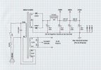
When you were previously building the non-adjustable bias version, (before you installed the 50 ohm wire-wound pots) the 6V6GT shared cathode resistor for each channel was 220 ohms. Now that you have installed the pots, and are building the version that has adjustable bias and DC balance, the series resistance provided by the two pots adds up to roughly 50-70 ohms for typical adjustment, so the 220 ohm resistor was decreased to 150 ohms so the total would be comparable. The 150 ohm value comes right out of Dave's original 8800 redux schematic. (Attached below)
BTW- Do you have an oscilloscope?
Notice I did not indicate which color of transformer leads (blue or brown) to connect where. We need an oscilloscope to determine that correctly, or you need to play "oscillation roulette", and reverse brown and blue if you get an awful loud screech from your expensive speakers. I'd use an oscilloscope and a dummy load, or at the very least super cheap thrift store speakers I could blow up.
BTW- Do you have an oscilloscope?
Notice I did not indicate which color of transformer leads (blue or brown) to connect where. We need an oscilloscope to determine that correctly, or you need to play "oscillation roulette", and reverse brown and blue if you get an awful loud screech from your expensive speakers. I'd use an oscilloscope and a dummy load, or at the very least super cheap thrift store speakers I could blow up.
Attachments

Yes on the oscilloscope - NO on the dummy loadWhen you were previously building the non-adjustable bias version, (before you installed the 50 ohm wire-wound pots) the 6V6GT shared cathode resistor for each channel was 220 ohms. Now that you have installed the pots, and are building the version that has adjustable bias and DC balance, the series resistance provided by the two pots adds up to roughly 50-70 ohms for typical adjustment, so the 220 ohm resistor was decreased to 150 ohms so the total would be comparable. The 150 ohm value comes right out of Dave's original 8800 redux schematic. (Attached below)
BTW- Do you have an oscilloscope?
Notice I did not indicate which color of transformer leads (blue or brown) to connect where. We need an oscilloscope to determine that correctly, or you need to play "oscillation roulette", and reverse brown and blue if you get an awful loud screech from your expensive speakers. I'd use an oscilloscope and a dummy load, or at the very least super cheap thrift store speakers I could blow up.
I strongly suggest building a dummy load, and picking up a signal generator. (Don't use the one built into the scope if it has one.) You will need these to build this amp correctly, tune the feedback, and verify it is stable. Part of the cost of making your own path away from pre-designed complete recipes is that you have to do more validation for yourself, and it can't be guessed at. It's time to take these steps, there is a lot of help, so no worries.
Testing of the amplifier requires a dummy load for the rated load, as measurements provided with an open load are not valid, and you don't want to be subjecting speakers to maximum output power. I have a diagram below for one channel of a simple 4 and 8 ohm load that allows you to switch the load open for those tests that require it. This will obviously support both 4 and 8 ohm amplifiers. Works great as-is for the types of lower power amplifiers you have built so far. If you get into the really big boys, limit test time to a few minutes, or add a heatsink and fan if you get really crazy.
Suggestions for the parts:
A nice smaller heavy aluminum box that will conduct heat nicely
Four 4 ohm 100 watt power resistors (need not be dual flange, but that is nice)
Two heavy ON-OFF-ON switches (available at Home Depot here)
Two 5-way speaker banana jack binding posts of your choice
Two RCA input connectors (for signal out to scope)
Basic RCA male to male interconnect cables
BNC to RCA adapters (greatly simplifies connectivity)
Two RCA female to dual RCA splitter cables
Build the load with two channels- many tests require you to drive and load both channels simultaneously. Don't skip the 4 ohm - open - 8 ohm functionality. (open is center switch position.) You will need to be able to switch the load open (with signal still going to scope) for stability testing. Use a heavy lamp cord for the wiring between the speaker terminals and the switch and resistors, wire to the RCA connector can be lighter, need not be shielded.
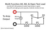
Testing of the amplifier requires a dummy load for the rated load, as measurements provided with an open load are not valid, and you don't want to be subjecting speakers to maximum output power. I have a diagram below for one channel of a simple 4 and 8 ohm load that allows you to switch the load open for those tests that require it. This will obviously support both 4 and 8 ohm amplifiers. Works great as-is for the types of lower power amplifiers you have built so far. If you get into the really big boys, limit test time to a few minutes, or add a heatsink and fan if you get really crazy.
Suggestions for the parts:
A nice smaller heavy aluminum box that will conduct heat nicely
Four 4 ohm 100 watt power resistors (need not be dual flange, but that is nice)
Two heavy ON-OFF-ON switches (available at Home Depot here)
Two 5-way speaker banana jack binding posts of your choice
Two RCA input connectors (for signal out to scope)
Basic RCA male to male interconnect cables
BNC to RCA adapters (greatly simplifies connectivity)
Two RCA female to dual RCA splitter cables
Build the load with two channels- many tests require you to drive and load both channels simultaneously. Don't skip the 4 ohm - open - 8 ohm functionality. (open is center switch position.) You will need to be able to switch the load open (with signal still going to scope) for stability testing. Use a heavy lamp cord for the wiring between the speaker terminals and the switch and resistors, wire to the RCA connector can be lighter, need not be shielded.
You are going to need a stand-alone signal generator. The signal generator built into the scope will not be useful here- you need to be able to adjust output level (amplitude) and the one in your scope is only a fixed or very limited amplitude. Plus, you want to be able to operate the signal generator and scope independently.
I have this model here from Amazon. It's cheap but it works great. It does not have a battery in it- it is powered from a 5V USB phone charger, (not included) which tends to inject noise. I ended up using stick-on Velco to stick a cheap Walmart USB charge vault onto the back of mine, and shortened the power cable to 3" long to plug them together. Now I have a "rechargeable" signal generator that does not inject any noise.
Beware the "DC Offset" button- it can get turned on accidentally and cause problems. Also the "filter" button can roll off the edges of your square wave and cause problems if turned on accidentally. I took mine apart and removed both red button extensions, and made sure they were off- now we get along very much better now. The jinky knob on the right is for adjusting the output amplitude, hard to get it precisely to the right values sometimes, but it's small enough you don't accidentally bump it in the middle of a test. Nothing fancy, but it has all the necessary waveforms and is good enough.
I have this model here from Amazon. It's cheap but it works great. It does not have a battery in it- it is powered from a 5V USB phone charger, (not included) which tends to inject noise. I ended up using stick-on Velco to stick a cheap Walmart USB charge vault onto the back of mine, and shortened the power cable to 3" long to plug them together. Now I have a "rechargeable" signal generator that does not inject any noise.
Beware the "DC Offset" button- it can get turned on accidentally and cause problems. Also the "filter" button can roll off the edges of your square wave and cause problems if turned on accidentally. I took mine apart and removed both red button extensions, and made sure they were off- now we get along very much better now. The jinky knob on the right is for adjusting the output amplitude, hard to get it precisely to the right values sometimes, but it's small enough you don't accidentally bump it in the middle of a test. Nothing fancy, but it has all the necessary waveforms and is good enough.

if you have a blown up amplifier you can salvage the heat sink for the dummy load too. Mine is built in the carcass of an old car amp. I did 4x 8 ohms, and that will let me run 4, 8, or 16 ohm as needed with some jumpers, or 4x 8 ohm which I've used for fixing car amps.
More things to Order - again --- ugg ---trying to get a comprehensive list compiled -- looking at the cathode resistors _ per schematic 10 ohms at 1% are there ---other considerations here ?When you were previously building the non-adjustable bias version, (before you installed the 50 ohm wire-wound pots) the 6V6GT shared cathode resistor for each channel was 220 ohms. Now that you have installed the pots, and are building the version that has adjustable bias and DC balance, the series resistance provided by the two pots adds up to roughly 50-70 ohms for typical adjustment, so the 220 ohm resistor was decreased to 150 ohms so the total would be comparable. The 150 ohm value comes right out of Dave's original 8800 redux schematic. (Attached below)
BTW- Do you have an oscilloscope?
Notice I did not indicate which color of transformer leads (blue or brown) to connect where. We need an oscilloscope to determine that correctly, or you need to play "oscillation roulette", and reverse brown and blue if you get an awful loud screech from your expensive speakers. I'd use an oscilloscope and a dummy load, or at the very least super cheap thrift store speakers I could blow up.
I see - again a WIDE diff in cost - And I am assuming the 1% rating is consistent with its importance in the circuit - SO -- thoughts on One vers another - Other desirable Attributes Are ?
The 10 ohm resistors are used to measure the amount of cathode current that is flowing from each 6V6GT, so that the voltage between Ck and Dk = 0 when the two currents exactly balance. You are shooting for balance within a very small number of mA, so they need to be accurate. They don't burn a lot of power because they are such low value, so 1/2 watt is fine, even 1/4 watt will work. When I built mine I used a meter to find four that were as close as possible. Beyond the accuracy, there are really no other considerations- as far as type, make, etc.
These days, 1% accuracy resistors are very easy to come by. My preference is to buy a large kit of 1% tolerance metal film (1/2W preferably) resistors from Amazon like this one. These kits are "a mile wide and an inch deep" so you only get like 10 of each value, so I back fill with a kit that has fewer values but more of each value like this one. It's also nice to pick up a kit of 2W resistors for power dropping and cathode resistor use, like this one.
These days, 1% accuracy resistors are very easy to come by. My preference is to buy a large kit of 1% tolerance metal film (1/2W preferably) resistors from Amazon like this one. These kits are "a mile wide and an inch deep" so you only get like 10 of each value, so I back fill with a kit that has fewer values but more of each value like this one. It's also nice to pick up a kit of 2W resistors for power dropping and cathode resistor use, like this one.
Still working on a order --- I see the 150ohm resistor ( cathode ) is called out at 5watts - is that overkill as the pot feeding it is a 2watt unit -- also Is it important to have a particular type---- and tolerance 1% OR ?When you were previously building the non-adjustable bias version, (before you installed the 50 ohm wire-wound pots) the 6V6GT shared cathode resistor for each channel was 220 ohms. Now that you have installed the pots, and are building the version that has adjustable bias and DC balance, the series resistance provided by the two pots adds up to roughly 50-70 ohms for typical adjustment, so the 220 ohm resistor was decreased to 150 ohms so the total would be comparable. The 150 ohm value comes right out of Dave's original 8800 redux schematic. (Attached below)
BTW- Do you have an oscilloscope?
Notice I did not indicate which color of transformer leads (blue or brown) to connect where. We need an oscilloscope to determine that correctly, or you need to play "oscillation roulette", and reverse brown and blue if you get an awful loud screech from your expensive speakers. I'd use an oscilloscope and a dummy load, or at the very least super cheap thrift store speakers I could blow up.
You're right, it's overkill. For two 6V6GT tubes in one channel, Dave called for 12V across the 150 ohm resistor. That is 12V ÷ 150 = 80mA for the pair (40mA each), so the actual power burned in the resistor P = I^2*R or V^2/R so either 0.080^2*150 or 12^2/150 = 0.96W or call it 1 watt. Generally you want a resistor to be rated for about twice the actual power it will burn for good reliability, so a 2W resistor would be "sufficient". I would rather that the cathode resistance be nice and stable across temperature, so I choose one that can handle the 1W without getting too hot, which is why 5W is suggested. Any sort will do, can be a metal oxide, or a wire-wound ceramic. It is fully bypassed with a big electrolytic capacitor so the electrical properties of the resistor itself really does not affect the circuit. I prefer the ceramic type, like these from Amplified Parts. The tolerance of those tends to be pretty good- like +/-5%, which is good enough. The actual bias will be adjustable with the bias pot, so any difference between the two cathode resistors will just be dialed out anyway.Still working on a order --- I see the 150ohm resistor ( cathode ) is called out at 5watts - is that overkill as the pot feeding it is a 2watt unit -- also Is it important to have a particular type---- and tolerance 1% OR ?
It's good practice to work through the power calculation for each resistor in a given design- usually there are enough voltages listed on the schematic to be able to figure the power burned in each. You will find many draw very tiny amounts of power, and some will surprise you at how much power they draw and those will likely need to be up-sized for best reliability. Better to find this with your pencil than with the smoke detector.
I see the logic - reasoning - for the extra Headroom ??? for the resistor , and it seems that other elements can be--- or likely to be subject to a value that is correct KINDA -- ok with that in mind I see the 1000 ohm50volt cap - another value I do not have ---- is that a value that can be fudged ?-- guessing that the 20% rule would apply - Just a guess though --- beyond that I am in the dark ---I suppose if I knew it's purpose - the question would become obvious - -Still working on a order --- I see the 150ohm resistor ( cathode ) is called out at 5watts - is that overkill as the pot feeding it is a 2watt unit -- also Is it important to have a particular type---- and tolerance 1% OR ?
Reposted the schematic below. There are two different caps of this value. Either can be a wide range of values. For the capacitor at the cathodes of the 6V6GT tubes, I will typically use 100uF at 100V, or 470uF at 25V, whatever I have on hand, as long as it is more than 100uF, and rated at a voltage of 25V or greater. (Higher voltage rating again gives better reliability.)
The second 1000uF @ 50V cap, at the cathode of the 6EU7 is equally flexible. Try to use something greater than 100uF, 470uF would be better, and it can be rated at very low voltage, as low as 16V or so.
The coupling caps (the 0.022uF @ 630V) have some flexibility, and can be as large as 0.1uF for your better transformers. The smaller coupling cap between the two 6EU7 triodes (the 0.047uF cap) can be a larger value, as it's not very critical.
The feedback capacitor (the silver mica 500V 750pF cap) is just a guess, as we have not characterized your performance with your specific output transformers. You might order a handful of values, (in pairs) of 200pF, 300pF, 680pF and 800pF so you have a shot of finding a parallel combination that gives the best performance.
The stability enhancing frequency limiting cap (the optional 100pF circled in dotted line) should also be on hand in case you get oscillation. That should also be a silver mica as above.
The second 1000uF @ 50V cap, at the cathode of the 6EU7 is equally flexible. Try to use something greater than 100uF, 470uF would be better, and it can be rated at very low voltage, as low as 16V or so.
The coupling caps (the 0.022uF @ 630V) have some flexibility, and can be as large as 0.1uF for your better transformers. The smaller coupling cap between the two 6EU7 triodes (the 0.047uF cap) can be a larger value, as it's not very critical.
The feedback capacitor (the silver mica 500V 750pF cap) is just a guess, as we have not characterized your performance with your specific output transformers. You might order a handful of values, (in pairs) of 200pF, 300pF, 680pF and 800pF so you have a shot of finding a parallel combination that gives the best performance.
The stability enhancing frequency limiting cap (the optional 100pF circled in dotted line) should also be on hand in case you get oscillation. That should also be a silver mica as above.
Another question about the bias section - First off i was under the impression that each Pot was- a adjustment for each tube - (As the DGSE1 ) I see--- I was mistaken -- or so it looks at least to me _ The first pot is addressing any Lack of Balance ? -- off of the plates of the 6eu7s converging on a common point --- (through the 47 ohm resistors ) then into a second POT where a common ( voltage ) is dialed in for the Pair of tubes --Are they adjusted as a PAIR ? Seems so --- thus the reasonably matched directive ---Please correct me if that is incorrect ---Reposted the schematic below. There are two different caps of this value. Either can be a wide range of values. For the capacitor at the cathodes of the 6V6GT tubes, I will typically use 100uF at 100V, or 470uF at 25V, whatever I have on hand, as long as it is more than 100uF, and rated at a voltage of 25V or greater. (Higher voltage rating again gives better reliability.)
The second 1000uF @ 50V cap, at the cathode of the 6EU7 is equally flexible. Try to use something greater than 100uF, 470uF would be better, and it can be rated at very low voltage, as low as 16V or so.
The coupling caps (the 0.022uF @ 630V) have some flexibility, and can be as large as 0.1uF for your better transformers. The smaller coupling cap between the two 6EU7 triodes (the 0.047uF cap) can be a larger value, as it's not very critical.
The feedback capacitor (the silver mica 500V 750pF cap) is just a guess, as we have not characterized your performance with your specific output transformers. You might order a handful of values, (in pairs) of 200pF, 300pF, 680pF and 800pF so you have a shot of finding a parallel combination that gives the best performance.
The stability enhancing frequency limiting cap (the optional 100pF circled in dotted line) should also be on hand in case you get oscillation. That should also be a silver mica as above.
View attachment 3827697
View attachment 3827698
Reposted the schematic below. There are two different caps of this value. Either can be a wide range of values. For the capacitor at the cathodes of the 6V6GT tubes, I will typically use 100uF at 100V, or 470uF at 25V, whatever I have on hand, as long as it is more than 100uF, and rated at a voltage of 25V or greater. (Higher voltage rating again gives better reliability.)
The second 1000uF @ 50V cap, at the cathode of the 6EU7 is equally flexible. Try to use something greater than 100uF, 470uF would be better, and it can be rated at very low voltage, as low as 16V or so.
The coupling caps (the 0.022uF @ 630V) have some flexibility, and can be as large as 0.1uF for your better transformers. The smaller coupling cap between the two 6EU7 triodes (the 0.047uF cap) can be a larger value, as it's not very critical.
The feedback capacitor (the silver mica 500V 750pF cap) is just a guess, as we have not characterized your performance with your specific output transformers. You might order a handful of values, (in pairs) of 200pF, 300pF, 680pF and 800pF so you have a shot of finding a parallel combination that gives the best performance.
The stability enhancing frequency limiting cap (the optional 100pF circled in dotted line) should also be on hand in case you get oscillation. That should also be a silver mica as above.
View attachment 3827697
View attachment 3827698
Almost did not see your question, buried inside a quote like that. One pot (the "Bias" pot) adjusts the combined total bias current for the two tubes in a channel. The other pot (the "DC BAL" pot) balances that current like a teeter-totter between the two tubes. So, you adjust both- adjust the BALance so there is zero volts between Ck and Dk, then adjust the BIAS bias pot until you read the desired voltage (12V if I remember, let me verify) between points T and K.Another question about the bias section - First off i was under the impression that each Pot was- a adjustment for each tube - (As the DGSE1 ) I see--- I was mistaken -- or so it looks at least to me _ The first pot is addressing any Lack of Balance ? -- off of the plates of the 6eu7s converging on a common point --- (through the 47 ohm resistors ) then into a second POT where a common ( voltage ) is dialed in for the Pair of tubes --Are they adjusted as a PAIR ? Seems so --- thus the reasonably matched directive ---Please correct me if that is incorrect
There are a pair of these pots for each channel.
Thank you -when I discarded the notion of what I had done with the dgse 1 - it became easy-er-- to understand - and the description ( from you ) is conformation - thank youAlmost did not see your question, buried inside a quote like that. One pot (the "Bias" pot) adjusts the combined total bias current for the two tubes in a channel. The other pot (the "DC BAL" pot) balances that current like a teeter-totter between the two tubes. So, you adjust both- adjust the BALance so there is zero volts between Ck and Dk, then adjust the BIAS bias pot until you read the desired voltage (12V if I remember, let me verify) between points T and K.
There are a pair of these pots for each channel.
In looking Again at things to order --- MY computer or mouser deleted my Basket --- anyway --I see a couple of Items that I am going to need -- BUT thought I had better check values again - as I mentioned I only have a couple 16v 1000 uf caps - SO i may as well get the 50v versions. The 100 pf caps are also not in the parts bin.Almost did not see your question, buried inside a quote like that. One pot (the "Bias" pot) adjusts the combined total bias current for the two tubes in a channel. The other pot (the "DC BAL" pot) balances that current like a teeter-totter between the two tubes. So, you adjust both- adjust the BALance so there is zero volts between Ck and Dk, then adjust the BIAS bias pot until you read the desired voltage (12V if I remember, let me verify) between points T and K.
There are a pair of these pots for each channel.
d
Sorry to bother - Just wanted to confirm a couple Items for the mouser order -- I am going to need some 100 ohm resistors for the 6v6s I do not see any specifics though -- 1watt 2 more less ? and tolerance is ? looks like they are expose to 300 or so volts.Almost did not see your question, buried inside a quote like that. One pot (the "Bias" pot) adjusts the combined total bias current for the two tubes in a channel. The other pot (the "DC BAL" pot) balances that current like a teeter-totter between the two tubes. So, you adjust both- adjust the BALance so there is zero volts between Ck and Dk, then adjust the BIAS bias pot until you read the desired voltage (12V if I remember, let me verify) between points T and K.
There are a pair of these pots for each channel.
In the NFL I see a 1.3k again is there a values I need to keep in mind ?
The 10 ohm cathode 1% resistors - rated at ? - it looks as though after the 150 ohm 5 watts---there is probably not much there - 12 volts or so ?
Thought I had the order SET -- BUT either mouser or my computer thought otherwise and-- poof it was gone