• The move to the new server is done. There are some software and database maintenance updates in process. This has us passing the hat around to help out. We appreciate any donations. Seriously, even a dollar helps. The payment page may be found here - https://www.audiokarma.org/support.html

ANOTHER - Impulse buy -- Magnavox 8802

Thats the Scott part number. I do not know Scott things well enough to tell you what that came out of but a 4K primary for an EL34 type isn't completely unreasonable. I think Scott used those in the 272? Forget the number but its their big boy integrated amplifier.
 
Thats the Scott part number. I do not know Scott things well enough to tell you what that came out of but a 4K primary for an EL34 type isn't completely unreasonable. I think Scott used those in the 272? Forget the number but its their big boy integrated amplifier.
Thought I had seen that model (Scott ) transformer but the 4k x 2 is confusing - Just wondering - if the 2 wires ( if that is being referenced ?) were ( or could be additive equaling a 8 k primary option - or if that feature is for another purpose ?
I have see options like that for other transformers for similar choices 4 and 6 k post's (or the like ) for primary impedance needs ?- as a example
Just trying to put the pieces together -
 
no idea on that, usually OE transformers don't have multiple impedance wiring options since they are designed for a single application.
 
Thought I had seen that model (Scott ) transformer but the 4k x 2 is confusing - Just wondering - if the 2 wires ( if that is being referenced ?) were ( or could be additive equaling a 8 k primary option - or if that feature is for another purpose ?
I have see options like that for other transformers for similar choices 4 and 6 k post's (or the like ) for primary impedance needs ?- as a example
Just trying to put the pieces together -

no idea on that, usually OE transformers don't have multiple impedance wiring options since they are designed for a single application.
yea that seems logical - - If it was easy and served other amps in your product line -- Perhaps -- but otherwise Why would you do that -- --Think I will put the question on the back burner - for now -Still an interesting question though-
 
Those look really good and should be quite amazing. Do you have measurements on those bad boys? Might be looking at a custom chassis . . .
I re- vested your remarks and Am thinking you are concerned with the SIZE of the Sansui's-- and well - i should be as well- if they don't fit it's a problem -To ward off the potential problem - I looked again on the BAY and found a pair of Harman Kardon a-300 outputs also designed for the 6v6 tube set --And at 30 each - 60 for the pair they seemed cheap so i gave him my money - Sometimes I see a ruler next to the Items - do wish that was more of a common practice
IN doing a search the transformers they are described as very small (compared to what )- how small -who knows - SOMEONE ??--so at this point I will have 2 sets to choose from - and of course the 4 ohm stock ones -
 
Ok (rolling up sleeves . . .) The 8802 is an amp that will require significant mods (more than the 8600, fewer than the 9300) to correct a myriad of problems from Magnavox- I think this is a great next step for your progression- having rebuilt a stock 8600, a "Twisted Sister" 6AQ5 based custom 8600 style variant, and hoping in the future to rebuild a 9300- The 8800 is the perfect "stepping stone" in that journey.

At a high level, you will want to do away with the puny 6CA4 rectifier- it was excellent for the low-power 8600 design, but has no place on a stereo push-pull amp- it's running at it's limit, lowers an already too-low high voltage, and causes bad sag and droop in the power supply. Conversion to diode rectification, and the addition of a filter choke will be required for any sort of decent performance.

The two problems that I have with Dave G's writeup on the 8800 is that he never posts a schematic of the modified power supply (It's easy enough to glean from the text, but it's a large missing piece for those just looking for a recipe) and he included adjustable bias, DC current balance, and AC distortion balance controls, mostly to compensate for the sub-par output transformers. These controls are all very nice to have, but significantly complicates an otherwise straight-forward design, and requires extra work and opportunities for mistakes to unroll those mods from the one (stock OPT) schematic that is given. Again, this is covered in the text, but not in schematic form.

I built a push-pull 6AQ5 amp, "The Mirror Mite", which was based heavily upon Dave's 8800 redesign. It incorporated the bias adjustment and DC current balance, and it sure sounds nice, and I like the controls, but they do significantly increase the size and complexity of the build.

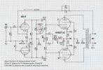
I recently helped a friend who wanted to rebuild an 8800 without those controls, and I took the time to draw up a nice schematic of one channel with Dave's recipe without those controls, and the modified power supply, shown below. The cathode resistor and feedback cap are tentative, and can be adjusted to fine tune the amp to your particular voltages and output transformers.

As far as output transformers- Anything in the roughly 10K plate to plate impedance will work well. The stock iron is pretty meager, and almost anything is a significant improvement, especially an 8 ohm output. 6V6GT push-pulls sound mighty nice, and better iron is a worthwhile investment here.


View attachment 3750357

View attachment 3750359

So it looks like the feedback is In the works --- A work in progress --- About the impute -
secondly -- I don't plan on a volume knob - Just confirming - the plan is to Ignore the pot and just go directly into the tube - is there a capacitor required ?
 
Feedback compensation capacitor will have to be determined from your testing with a dummy load, signal generator, and oscilloscope, otherwise we're just shooting in the dark. I don't think anybody has used those particular output transformers, so no idea on a "guesstimate" value.

Yes- I removed the volume control from my first schematic to match Dave's front end. No (47pF) capacitor required if you go with Dave's front end.

== Edit- outdated schematic removed to avoid confusion- updated schematic appears below. ==
 
Last edited:
Feedback compensation capacitor will have to be determined from your testing with a dummy load, signal generator, and oscilloscope, otherwise we're just shooting in the dark. I don't think anybody has used those particular output transformers, so no idea on a "guesstimate" value.

Yes- I removed the volume control from my first schematic to match Dave's front end. No (47pF) capacitor required if you go with Dave's front end.

View attachment 3815749
Yes The feedback - will need some attention -
ON the impute I did see as low as 10k prior to the first tube - So thought Better ask --thanks for the reply .
A update on the Sansui transformers - got a box from Japan with ONLY 1 Transformer !!- seller apologized ---He was GOING TO TRY AND SOURCE ANOTHER ---But I got ant-sey saw another and Use the buy it now feature for a second - however it has a slightly different number -Rather Letter - that is It is a W version not the H-15-8 several years between - -Different??-- probably significantly so ??? we will see --- Always something - right ?
 
ON the impute I did see as low as 10k prior to the first tube - So thought Better ask --thanks for the reply .
That first resistor, 10K or 33K or 47K forms a low-pass filter going into the 6EU7/12AX7 grid. The value of that resistor can be adjusted to limit how high of frequencies are allowed to enter the input. A 10K ohm alone allows up to 80-90kHz, a 33K ohm with 47pF to ground allows up to about 23kHz, and a 47k by itself allows up to about 20kHz, so is basically equivalent, but saves you the cap. This frequency limiting is wise because it can help eliminate instability in the amplifier when input and output cables talk to each other at high frequencies.
 
The Eico ST40 outputs are likely very good and at about 8k would fill the bill. MPS has what is apparently a very good version of the Dynaco ST/SCA-35 output. The Heathkit 51-29 and 51-30 outputs are also quite good and are 10k units with 50% screen taps.
A gentleman on the bay - is listing A heathkit output 51-29 and describes the impedance as 7.5 k - did you measure your transformers @10k ? - further If I remember Dave used the heath 51-58s ? - in his mod of the magnavox 8802 ---I could be wrong - -- again another impedance -- am i overthinking this ? Just exploring options -
 
A gentleman on the bay - is listing A heathkit output 51-29 and describes the impedance as 7.5 k - did you measure your transformers @10k ? - further If I remember Dave used the heath 51-58s ? - in his mod of the magnavox 8802 ---I could be wrong - -- again another impedance -- am i overthinking this ? Just exploring options -
 
To muddy the water - _I bought a set of the 51-29 heaths --- despite the 7.5 k primary Notation --
On the Tranola site Dave G contrast the z565 dynacos with the 51- 29s and wrote they they (the heaths ) have a 10k primary- OK A mystery !
 
A gentleman on the bay - is listing A heathkit output 51-29 and describes the impedance as 7.5 k - did you measure your transformers @10k ? - further If I remember Dave used the heath 51-58s ? - in his mod of the magnavox 8802 ---I could be wrong - -- again another impedance -- am i overthinking this ? Just exploring options -
Where does the 7.5K value come from?
Could be from the reference to the 51-58 outputs from an AA-100. I think they are around 7.5k. DaveG used them in his Fisher SA-100 clone.
 
ah, I must have gotten lost somewhere with the transformer numbers being discussed.

was just curious if it was a Sams value or something, those occasionally had mistakes.
 
That first resistor, 10K or 33K or 47K forms a low-pass filter going into the 6EU7/12AX7 grid. The value of that resistor can be adjusted to limit how high of frequencies are allowed to enter the input. A 10K ohm alone allows up to 80-90kHz, a 33K ohm with 47pF to ground allows up to about 23kHz, and a 47k by itself allows up to about 20kHz, so is basically equivalent, but saves you the cap. This frequency limiting is wise because it can help eliminate instability in the amplifier when input and output cables talk to each other at high frequencies.
Some of these measures -(choices ie 10k 33 ect ) seem to be preventive measures in nature == anticipatory - mitigating oscillation as a example -
Examining Dave's 8802 - his mod anyway-- I see the 6eu7 populated - and well; it seems very cluttered -- Curious -- - I have seen recommendation of keeping some elements close to the tube - but it seems very busy - Nicely done, but cluttered --are there more important elements and the not so important - thinking about a tag - strip to de clutter -
That first resistor, 10K or 33K or 47K forms a low-pass filter going into the 6EU7/12AX7 grid. The value of that resistor can be adjusted to limit how high of frequencies are allowed to enter the input. A 10K ohm alone allows up to 80-90kHz, a 33K ohm with 47pF to ground allows up to about 23kHz, and a 47k by itself allows up to about 20kHz, so is basically equivalent, but saves you the cap. This frequency limiting is wise because it can help eliminate instability in the amplifier when input and output cables talk to each other at high frequencies.
 
Some of these measures -(choices ie 10k 33 ect ) seem to be preventive measures in nature == anticipatory - mitigating oscillation as a example -
Examining Dave's 8802 - his mod anyway-- I see the 6eu7 populated - and well; it seems very cluttered -- Curious -- - I have seen recommendation of keeping some elements close to the tube - but it seems very busy - Nicely done, but cluttered --are there more important elements and the not so important - thinking about a tag - strip to de clutter -
 

Attachments

  • SAM_2420(3).JPG
    SAM_2420(3).JPG
    100.3 KB · Views: 16
Feedback compensation capacitor will have to be determined from your testing with a dummy load, signal generator, and oscilloscope, otherwise we're just shooting in the dark. I don't think anybody has used those particular output transformers, so no idea on a "guesstimate" value.

Yes- I removed the volume control from my first schematic to match Dave's front end. No (47pF) capacitor required if you go with Dave's front end.

View attachment 3815749
So I was looking for some visual clues for the --- 6eu7 tube --- set up ( connections ) and came across Daves posting of the original Modification - His work is very tidy - however unless it is my imagination ----------the Photo if used as a guide - IS different than the one (the schematic and values ) you are recommending - Just wanted to confirm the one ABOVE -is what i am shooting for -- correct ?
Still waiting for (it's in the mail ) stuff - and as I will need some additional values - I should get use to it ---
I do wish I had paid more attention to the simple variation - recommended -- I know --- Water under the bridge
 
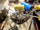
Well, I will say it looks like your soldering is getting better. Those components are really tight in that picture you posted. As long as nothing is touching and shorting, it should be OK- but keep in mind, when you cramp stuff in there so tightly it becomes a real challenge to change anything afterwards. The decision of whether, where, and how big of a terminal strip you should place is part of the artform that is amp building- and also why when you were whingeing about how to build your 8600 I strongly advised doing sketches on paper to work out where everything will connect- you can go component by component and in the end paint yourself into a corner. The sketch lets you work out every connection ahead of time and iterate quickly on the best arrangement to make it quick and easy to build, and relatively easy to service later. It looks like you are doing pretty good though.

Yes, there are some minor component differences between Dave's schematic and what I have drawn for you. I'm not going to dive into Dave's under-chassis build photos to figure out what differences you are mentioning- are there any you would like to call out?

Yes, the above schematic (now disappeared from above as it is outdated, and appearing here now) is the one you are building to.
Not to frustrate you, but I have made one additional (*Optional) modification. The 100pF capacitor across the 220K resistor (that is circled with a dashed line) is extra insurance. I don't remember whether you have an oscilloscope, signal generator, or dummy load, and you are setting about the somewhat risky venture of building and amplifier with perhaps not the equipment to properly verify feedback compensation or stability tuning. The 100pF capacitor was used in the original design as a "safety margin" to make sure the amplifier was stable under different conditions. Also, the feedback cap (the one at the top center, that was labelled "TBD" is now 750pF. This was the correct value for both versions of Dave's 8800 redesign, and is a fair guess for what you will need with your new transformers. Please let me know if you have questions/concerns.


S_Swanson_8802_Channel_DC+Bias_Adj_Sch_tentative.jpg
 
Back
Top Bottom