Hi all,
This is my first AK post, so please excuse any missteps. Sorry, this is a long post. For those wanting to skip the background, please jump to my QUESTION below. I also added a TIP at the end of this post for dealing with the peanut brittle plug.
BACKGROUND
Let me first sincerely thank all of you who have contributed their knowledge, expertise, and tips to this forum over the years! Discovering vintage speaker restoration through this forum has really helped preserve my sanity during my days holed up from the pandemic this past year. Although I must say at this point it’s now become a borderline obsession, with a pair of AR 4x’s and KLH 17’s under my belt, both brought back to life (recaps, resealing and cabinet work) to sound and look beautiful!
It was during my research on my KLH 17’s that I discovered the curious design of the early model KLH 6’s with their drivers epoxied to the baffle, peanut brittle square plug, and non-removable grilles. (As others have stated, “what was Henry thinking?”). I made a mental note early on “make sure not to pick up any of these by mistake”. Well silly me, after recently coming across a pair of 6’s on CL that “didn’t work” but cabinets in what looked like mint condition for cheap, and after reading that Henry thought he “got it right” with the 6’s, I decided, what the hell, I guess I’m ready for a new challenge!
So I now own a beautiful looking pair of early model KLH 6’s, that do work but both with diminished sound from the tweeters. The serial numbers are far apart (20xxx and 30xxx), but cabinets look identical and both have rusted coloring on the grille cloth from age so looks like they have been stored together for a long time. So maybe one was returned and replaced early on after purchase. The 20xxx speaker has the military grade oil filled “tin can” caps, and the 30xxx speaker has the more common “brick red” caps similar to what was in my KLH 17’s. Both have epoxied woofers and tweeters.
The newer speaker has barely any tweeter output (not surprising with this type of cap) The older speaker with the oil filled caps definitely has more tweeter output but still significantly diminished, which surprised me after what I have read about the oil filled caps aging well. So my plan is to fully recap the newer one, and with the older one start with replacing just the one oil filled smaller cap bundled with the switch and resistors. Then compare with the other speaker before deciding to replace the larger 2nd oil filled cap. I also plan to replace all resistors; I know — many suggest just leaving the old ones, but they are cheap enough so thought I would go for it for the first time.
QUESTION - REQUEST FOR HELP
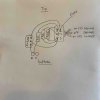
Now my request for help. I stupidly forgot to take a photo when breaking up the peanut brittle and disassembling the crossover of the first newer speaker, so failed to take note of the cap, resistors sand 3-way switch connections. With the 2nd older speaker I did take photos of the crossover and planned to use this as a reference for both. But when comparing my photo with the crossover spec that is included in the KLH 6 manual it does not seem to match (although I must admit I’ve intently studied this KLH 6 x-over diagram and I’m very confused by it.) I read in multiple posts that the KLH 17 crossover is identical to the KLH 6. But in looking at my photos of my earlier KLH 17 work, the connections are different than my KLH 6. And furthermore, the KLH 17 only has the two terminal posts, and not the three like on the KLH 6, so not sure how comparable.
I would greatly appreciate if anyone can provide an easy to understand diagram of the connections of the caps, resistors and terminals on the 3-way switch for the early model KLH 6? In particular, the discrepancy I see is with how the resistors connect to the 3-way switch terminals (i.e, Normal, Decrease, Increase). Thank you.
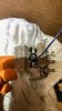
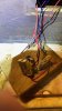
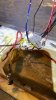
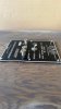
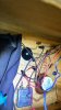
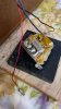
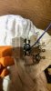
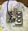
I have uploaded some photos of the older KLH 6 with the oil filled caps.
TIP
Here is a tip on dealing with the peanut brittle if you plan to also replace the resistors. I first chipped out the block of peanut brittle as others have suggested. I ended up preferring a hammer and old flathead screw driver. I started with a chisel but it cut through one of the wires (not good if you’re wanting to keep track of connections, and the sharp blade of the chisel is not really necessary. (I read how some have tackled the brittle removal using heat to melt it away, but that sounded like you would be left with a sticky mess so I decided against it). Here’s the new bit that I have not seen mentioned before (maybe for good reason!?). After chipping out the bock, I soaked the block of brittle and electronics in rubbing alcohol, which dissolved all the brittle after an hour or two to leave a nice clean switch. Since I wasn’t keeping the resistors or capacitor I wasn’t concerned about how this might affect them, and seems like the alcohol dries pretty clean, so as not to damage the switch. Other solvents would probably also work, but I had alcohol on hand and it’s not very harsh so thought it would be a good choice. After the switch dried completely I sprayed a bit of electronics silicon lube/de-ox into the toggle switch and worked it in there. I expect it will work fine.
This is my first AK post, so please excuse any missteps. Sorry, this is a long post. For those wanting to skip the background, please jump to my QUESTION below. I also added a TIP at the end of this post for dealing with the peanut brittle plug.
BACKGROUND
Let me first sincerely thank all of you who have contributed their knowledge, expertise, and tips to this forum over the years! Discovering vintage speaker restoration through this forum has really helped preserve my sanity during my days holed up from the pandemic this past year. Although I must say at this point it’s now become a borderline obsession, with a pair of AR 4x’s and KLH 17’s under my belt, both brought back to life (recaps, resealing and cabinet work) to sound and look beautiful!
It was during my research on my KLH 17’s that I discovered the curious design of the early model KLH 6’s with their drivers epoxied to the baffle, peanut brittle square plug, and non-removable grilles. (As others have stated, “what was Henry thinking?”). I made a mental note early on “make sure not to pick up any of these by mistake”. Well silly me, after recently coming across a pair of 6’s on CL that “didn’t work” but cabinets in what looked like mint condition for cheap, and after reading that Henry thought he “got it right” with the 6’s, I decided, what the hell, I guess I’m ready for a new challenge!
So I now own a beautiful looking pair of early model KLH 6’s, that do work but both with diminished sound from the tweeters. The serial numbers are far apart (20xxx and 30xxx), but cabinets look identical and both have rusted coloring on the grille cloth from age so looks like they have been stored together for a long time. So maybe one was returned and replaced early on after purchase. The 20xxx speaker has the military grade oil filled “tin can” caps, and the 30xxx speaker has the more common “brick red” caps similar to what was in my KLH 17’s. Both have epoxied woofers and tweeters.
The newer speaker has barely any tweeter output (not surprising with this type of cap) The older speaker with the oil filled caps definitely has more tweeter output but still significantly diminished, which surprised me after what I have read about the oil filled caps aging well. So my plan is to fully recap the newer one, and with the older one start with replacing just the one oil filled smaller cap bundled with the switch and resistors. Then compare with the other speaker before deciding to replace the larger 2nd oil filled cap. I also plan to replace all resistors; I know — many suggest just leaving the old ones, but they are cheap enough so thought I would go for it for the first time.
QUESTION - REQUEST FOR HELP
Now my request for help. I stupidly forgot to take a photo when breaking up the peanut brittle and disassembling the crossover of the first newer speaker, so failed to take note of the cap, resistors sand 3-way switch connections. With the 2nd older speaker I did take photos of the crossover and planned to use this as a reference for both. But when comparing my photo with the crossover spec that is included in the KLH 6 manual it does not seem to match (although I must admit I’ve intently studied this KLH 6 x-over diagram and I’m very confused by it.) I read in multiple posts that the KLH 17 crossover is identical to the KLH 6. But in looking at my photos of my earlier KLH 17 work, the connections are different than my KLH 6. And furthermore, the KLH 17 only has the two terminal posts, and not the three like on the KLH 6, so not sure how comparable.
I would greatly appreciate if anyone can provide an easy to understand diagram of the connections of the caps, resistors and terminals on the 3-way switch for the early model KLH 6? In particular, the discrepancy I see is with how the resistors connect to the 3-way switch terminals (i.e, Normal, Decrease, Increase). Thank you.
I have uploaded some photos of the older KLH 6 with the oil filled caps.
TIP
Here is a tip on dealing with the peanut brittle if you plan to also replace the resistors. I first chipped out the block of peanut brittle as others have suggested. I ended up preferring a hammer and old flathead screw driver. I started with a chisel but it cut through one of the wires (not good if you’re wanting to keep track of connections, and the sharp blade of the chisel is not really necessary. (I read how some have tackled the brittle removal using heat to melt it away, but that sounded like you would be left with a sticky mess so I decided against it). Here’s the new bit that I have not seen mentioned before (maybe for good reason!?). After chipping out the bock, I soaked the block of brittle and electronics in rubbing alcohol, which dissolved all the brittle after an hour or two to leave a nice clean switch. Since I wasn’t keeping the resistors or capacitor I wasn’t concerned about how this might affect them, and seems like the alcohol dries pretty clean, so as not to damage the switch. Other solvents would probably also work, but I had alcohol on hand and it’s not very harsh so thought it would be a good choice. After the switch dried completely I sprayed a bit of electronics silicon lube/de-ox into the toggle switch and worked it in there. I expect it will work fine.




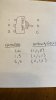
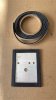
 I just tested connectivity with all combinations of paired connections and switch positions. I've attached a drawing of the a table of results, if that's useful.