• The move to the new server is done. There are some software and database maintenance updates in process. This has us passing the hat around to help out. We appreciate any donations. Seriously, even a dollar helps. The payment page may be found here - https://www.audiokarma.org/support.html

Another Stromberg Carlson Perfectempo Restoration...

hirscwi

AK Subscriber
Subscriber
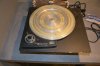
A very kind AK member decided that I needed another turntable and another project, and so I am now the proud owner of a vintage Stromberg Carlson Perfectempo!
DSC_4701.JPG
I know absolutely nothing about these tables but it was recommended by the guy who sent it my way...

Fortunately, @John Berard has a couple extremely helpful threads:

https://audiokarma.org/forums/index...fectempo-restoration-and-observations.889340/

https://audiokarma.org/forums/index...-anti-skate-to-older-unipivot-tonearm.889391/

I am indebted to Jon for this information. I can't hope to duplicate the insight and thoroughness of his threads (because I'm an undisciplined yahoo...) but thought I'd post my progress in hopes that it might be of interest to someone. If there's no interest I won't clog the airwaves...
 
Last edited:
Register to hide this ad
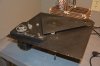
Here are some more photos that might be of interest. Compared to the one John restored, mine is the later version (as evidenced by the different color and cutout where the arm attaches). Mine uses a Papst motor instead of the General Industries used in the earlier version.

I have done nothing so far except to unpack the table ( a 10 minute process!). The guy I bought this from observed that it is "as if the TD124 and AR had a fat baby". Some observations:

- appears to be well engineered and quite substantially made
- the drive system, while a bit complicated, should function quite well and offers continuously variable speed
- the motor should respond well to replacing the run capacitor with a motor controller
- the platter is well made and nicely balanced
- I won't be using 45s on this table so I don't have to worry about the inherent VTA complication noted by John in his thread

My table did not include an arm but I am soon to be in receipt of a S-C arm that is correct for this table (albeit the early version). I haven't seen the arm yet but understand it needs to be replated. I've recently had a Triplanar arm completely reworked by Tim Corn and may ask him to work his magic on the S-C arm. I might also undertake myself depending in the complexity (would use a local plating firm).

My approach will be as follows:

- complete disassembly of the table (document with photos)
- clean all parts
- refinish the chassis. I like the maroon color of the earlier version, but may not be able to duplicate. I also like the silver/grey finish John used.
- send idler to be refinished - does anyone know if Terry is still refurbishing idler wheels?
- clean, replate, and rewire arm (likely Tim Corn)
- polish platter and fabricate new mat according to John's approach
- rebuild the motor. Initially I will use as originally made - i.e. with motor run film cap to proved the second phase. Subsequently I will install a 3-phase motor controller
- construct a plinth with a view to keeping it somewhat mid-century in design
- assemble and enjoy

DSC_4702.JPG DSC_4703.JPG DSC_4706.JPG DSC_4708.JPG DSC_4713.JPG
 
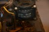
Some detail on the motor. This is a Papst motor. It is very similar to the ones used in the Empire 208 table and some of the Rek O Kut B12 tables. this motor is very substantial in my experience. It is extremely quite, producing only "swish" sound from the integrated cooling fins.
DSC_4709.JPG
It is a true 3-phase AC synchronous motor. In most implementations I've seen, a motor run capacitor (special type of film cap) provide a phase-shifted signal for the second lag. With this arrangement, the motor is receiving 0, 90 and 180 signals. It is designed for, and operates a bit better, with 0, 120 and 240 degree signals. Hence the reason for the external motor controller instead of the run cap. Does this really improve the sound? I can't say for sure but this is a DIY project and therefore overkill is always in order. There's a nice signal generator designed by Bill Carlin (owner of Phoenix Engineering - Falcon and Roadrunner manufacturer). It can drive 3 amps to produce the 3 phases for this motor. I've done it in the past for an Empire and am pleased with the results (remember the overkill maxim).

DSC_3233.JPG
 
I know that Il will need a cartridge at some point. The S-C arm has an effective mass of about 42 gram (!). I would greatly appreciate recommendations for cartridges that will work nicely with this table. I wonder if the Denon 103 would work? I have no experience with any arms of this vintage or high mass.

The arm is a unipivot and is damped. John includes some nice photos and diagrams of this arm so I won't include here. the arm does not have anti-skate as it didn't come into vogue until a few years after this table and probably wasn't needed for conical styli. In one of John's threads he shows an add-on a/s device that he built using 3D printing. I hope to impose on him to share the files so I can print one myself.

Suggestions for cartridges will be greatly appreciated.
 
Some detail on the motor. This is a Papst motor. It is very similar to the ones used in the Empire 208 table and some of the Rek O Kut B12 tables. this motor is very substantial in my experience. It is extremely quite, producing only "swish" sound from the integrated cooling fins.
View attachment 1780855
It is a true 3-phase AC synchronous motor. In most implementations I've seen, a motor run capacitor (special type of film cap) provide a phase-shifted signal for the second lag. With this arrangement, the motor is receiving 0, 90 and 180 signals. It is designed for, and operates a bit better, with 0, 120 and 240 degree signals. Hence the reason for the external motor controller instead of the run cap. Does this really improve the sound? I can't say for sure but this is a DIY project and therefore overkill is always in order. There's a nice signal generator designed by Bill Carlin (owner of Phoenix Engineering - Falcon and Roadrunner manufacturer). It can drive 3 amps to produce the 3 phases for this motor. I've done it in the past for an Empire and am pleased with the results (remember the overkill maxim).

View attachment 1780858
You sir, are a treasure trove of information!
Thank you for undertaking this magnificent masterpiece!
 
I know that Il will need a cartridge at some point. The S-C arm has an effective mass of about 42 gram (!). I would greatly appreciate recommendations for cartridges that will work nicely with this table. I wonder if the Denon 103 would work? I have no experience with any arms of this vintage or high mass.

The arm is a unipivot and is damped. John includes some nice photos and diagrams of this arm so I won't include here. the arm does not have anti-skate as it didn't come into vogue until a few years after this table and probably wasn't needed for conical styli. In one of John's threads he shows an add-on a/s device that he built using 3D printing. I hope to impose on him to share the files so I can print one myself.

Suggestions for cartridges will be greatly appreciated.

Carts:
Fairchild-SM-1. Or 225-b
empire 108

GE VR carts..... then Pritchards ADC carts

Shure M3D M7D / RS100

let me think of some others...
 
3 phase motor can be controlled very well with a variable frequency drive (VFD). The challenge will be finding one that outputs 120VAC. Most commercial ones that I have been involved with that run on 120VAC output 230VAC. You might want to research that. Does away with the amps and such.

BillWojo
 
I have used the Empire 108 and the GE VR 1000 in similar applications and have nothing but good things to say. Replacement stylii are available and of course Joseph Long can help with upgrades if you desire. Looks like you have your work cut out for you with this one. Nice project. Guess it'll be awhile before we see progress...?
 
3 phase motor can be controlled very well with a variable frequency drive (VFD). The challenge will be finding one that outputs 120VAC. Most commercial ones that I have been involved with that run on 120VAC output 230VAC. You might want to research that. Does away with the amps and such.

BillWojo
Thanks, that sounds like another interesting project. Are they generally a commercial device? Typical uses are?
 
I have used the Empire 108 and the GE VR 1000 in similar applications and have nothing but good things to say. Replacement stylii are available and of course Joseph Long can help with upgrades if you desire. Looks like you have your work cut out for you with this one. Nice project. Guess it'll be awhile before we see progress...?
Well, yes, I fear that progress will be slow because I involved myself in too many projects and I have help from my wife and daughter in determining how I can spend my time (and I thought I'd have more of that in retirement...)
 
Some detail on the motor. This is a Papst motor. It is very similar to the ones used in the Empire 208 table and some of the Rek O Kut B12 tables. this motor is very substantial in my experience. It is extremely quite, producing only "swish" sound from the integrated cooling fins.
View attachment 1780855
It is a true 3-phase AC synchronous motor. In most implementations I've seen, a motor run capacitor (special type of film cap) provide a phase-shifted signal for the second lag. With this arrangement, the motor is receiving 0, 90 and 180 signals. It is designed for, and operates a bit better, with 0, 120 and 240 degree signals. Hence the reason for the external motor controller instead of the run cap. Does this really improve the sound? I can't say for sure but this is a DIY project and therefore overkill is always in order. There's a nice signal generator designed by Bill Carlin (owner of Phoenix Engineering - Falcon and Roadrunner manufacturer). It can drive 3 amps to produce the 3 phases for this motor. I've done it in the past for an Empire and am pleased with the results (remember the overkill maxim).

View attachment 1780858


Thanks, that sounds like another interesting project. Are they generally a commercial device? Typical uses are?


3 phase motor can be controlled very well with a variable frequency drive (VFD). The challenge will be finding one that outputs 120VAC. Most commercial ones that I have been involved with that run on 120VAC output 230VAC. You might want to research that. Does away with the amps and such.

BillWojo

I have to step in and say something about motors , terminology and single-phase vs 3phase.

3-phase is a term used to describe three different conductors carrying alternating current voltages that are offset in time by one-third of the period. This is illustrated with sine waves thusly:
4785405B-0D4D-4F4F-A9C7-8A0D5F93A184.jpeg

A single-phase (one leg)120v motor can have three windings, But it isn’t a three-phase motor. One winding is a “starter” winding connected to the capacitor and this winding is what gets the motor turning when voltage is applied. The other two windings are what keeps the motor turning.

There is a motor that is called “single-phase” although it needs 208v or 220v/230/240v. It is actually needs 2 phases (or legs) still offset in time by 1/3.

A three phase motor (never 120v) rarely employees a capacitor, and Can have up to 12 windings.
3phase motors can be:
US 60hz-
208-230v/460 (this can also be described as 220/480)
Or European 50Hz:
220-240/380-415v (220/380)


There is no reason to control the speed of the motor on an idler drive.We want this motor to spin at a very steady speed. The platter speed is controlled by the conical drive of this table.

Speed control of a single phase motor:

2 most common ways is change the frequency of the line voltage the windings see or by changing the voltage seen by the windings thereby changing the rotational speed.

speed control of a 3-phase motor:
  1. Changing the number-of poles.
  2. Governing the supply frequency.
  3. Controlling the slip of the motor.
  4. Controlling the stator voltage.

I don’t think 3phase motors are used in turntables. 3phase motors are more efficient and are used in applications where mucho HP is needed.

VFD = variable frequency drives
Used in many applications. Chillers, cooling towers, compressors, HVAC equipment... and the small ones on conveyors, cooling fans, and in automation type manufacturing.

I hope I don’t sound persnickety, but I think these terms often get misused and misunderstood. :dunno:
I use to teach a course on this at our IBEW/NJACT

 
Last edited:
I'm a bit confused. The controller that I have used on other Papst motors puts out 3 signals, separated by 120 degrees, like in your diagram. As I understand it, a motor with a starter cap is a 2-phase and the starter is needed to get it rotating but then doesn't add anything. That coil will have a different resistance. The Papst motors are AC synchronous. That is the rotational speed is controlled by the frequency of the signals sent to it. They may be different than the fractional horsepower motors used in industrial equipment.
 
The motor controller I'm referring to was designed by Bill Carlin (Phoenix Engineering) and the design put into the public domain. I built it from that schematic. This controller uses a custom programmed microprocessor to generate 4 identical sine waves, at 0, 90, 120, and 240 degrees. They are the same amplitude (in this case, 2.5Vp-p). You don't use the 90 degree wave for this controller. These signals are then amplified and sent to the motor. If you connect to a 'scope (I have done) you will see 3 separate waves, just like in your original diagram. The frequency of these 3 sine waves is identical and adjustable. By changing the output frequency from the controller, the motor rotational speed changes.

In the Papst motor, there are 3 sets of coils. One end of each of these coils is connected together. The 3 input signals connect respectively to each of the coils, hence each coil peaks its magnetic flux at a slightly different time (because of the phase difference). These coils are equally spaced around the stator and the chanes in polarity of these coils spins the motor. I can't find my article but here's a link to a helpful video.


Also I'm attaching a crude diagram that shows how the signal causes the rotation.
 

Attachments

A very kind AK member decided that I needed another turntable and another project, and so I am now the proud owner of a vintage Stromberg Carlson Perfect Tempo!

I am excited for you Bill. But one must first know that Perfectempo is one word. :)
 
The motor controller I'm referring to was designed by Bill Carlin (Phoenix Engineering) and the design put into the public domain. I built it from that schematic. This controller uses a custom programmed microprocessor to generate 4 identical sine waves, at 0, 90, 120, and 240 degrees. They are the same amplitude (in this case, 2.5Vp-p). You don't use the 90 degree wave for this controller. These signals are then amplified and sent to the motor. If you connect to a 'scope (I have done) you will see 3 separate waves, just like in your original diagram. The frequency of these 3 sine waves is identical and adjustable. By changing the output frequency from the controller, the motor rotational speed changes.

In the Papst motor, there are 3 sets of coils. One end of each of these coils is connected together. The 3 input signals connect respectively to each of the coils, hence each coil peaks its magnetic flux at a slightly different time (because of the phase difference). These coils are equally spaced around the stator and the chanes in polarity of these coils spins the motor. I can't find my article but here's a link to a helpful video.


Also I'm attaching a crude diagram that shows how the signal causes the rotation.

apologies Bill, this thread is about your restoration of a marvelous piece of engineering. It’s not about my limited understanding of a motor controller that you built. I will clean up my above gobbledygook. I shall study :beatnik:.
 
3 outputs offset by 120 degrees is 3 phase.

A capacitor offsets by 90 degrees. A motor designed for use with a cap will have the windings arranged physically differently than one intended for use on proper 3 phase. Less coils too, 2 sets of windings vs 3. Feeding 120 offset power into something designed for 90 offset will make it vibrate more than it should. Same if you go the other way.

VFD is Variable Frequency Drive. Its how you slow down 3 phase motors. Also sometimes used to make 3 phase power from a single phase supply. Basically thats what your controller is, just intended for a smaller motor than a typical industrial drive is.

tl;dr, if its a real deal 3 phase motor, feed it 3 phase power. Tesla would be proud.
 
Back
Top Bottom