OK, here we go:
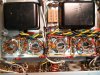
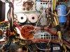
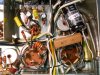
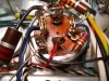
A) Each of the outputs is connected, in pairs, at pin 5 with either a red wire or a blue wire. Each pair is connected to one of the 10ohm just north in the pic. All blue and red wiring at pin 5 to 10ohm resistors go bye bye. In place, a single 10ohm 1/4 resistor on bare pin 5 to ground. Yes?
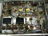
B) For screen stability resistors: working from tube at extreme left to right in pic, remove all wiring connecting the tubes at pin 4; connect a wire to pin 1 of each tube so that they are all connected. Attach 100ohm resistor between pin 1 and pin 4 of each tube. Pin 1 at tube on extreme right is connected to C-50. Yes?

A) Each of the outputs is connected, in pairs, at pin 5 with either a red wire or a blue wire. Each pair is connected to one of the 10ohm just north in the pic. All blue and red wiring at pin 5 to 10ohm resistors go bye bye. In place, a single 10ohm 1/4 resistor on bare pin 5 to ground. Yes?
B) For screen stability resistors: working from tube at extreme left to right in pic, remove all wiring connecting the tubes at pin 4; connect a wire to pin 1 of each tube so that they are all connected. Attach 100ohm resistor between pin 1 and pin 4 of each tube. Pin 1 at tube on extreme right is connected to C-50. Yes?