• The move to the new server is done. There are some software and database maintenance updates in process. This has us passing the hat around to help out. We appreciate any donations. Seriously, even a dollar helps. The payment page may be found here - https://www.audiokarma.org/support.html

Anyone ever bypass the Scott PEC filter 299 ?

billyz

Super Member
Not even sure what it does , is it part of the Scott Dynaural filter ? Does the Scott 233/299 series have a subsonic filter ? As in a fixed filter. The reason I ask is, I am rebuilding a Scott 233 and the line stage is very dynamic and full sounding, but the phono stage is lackluster and the low end seems rolled off . I have not recapped the phono stage yet, so maybe that will cure it.

I see the PEC 299 is in the line stage so that is not the problem. Just wondering if anyone else has bypassed it and the results. I usually find less is more .

I confess I am a bit confused by the Phono EQ PEC 222er filtering and thought it may have a Subsonic filter built in. I planned to remake it in discreet components and do not want to replicate a low filter if it has one fixed in it.

So I guess this really two questions.
 
Register to hide this ad
If i am not mistaken, the dynaural filter is an active filter. It has a tube in the circuit. Most Scotts have this as part of the phono circuit and so not being used unless the phono stage is used. Some Scott models have this on a switch so you can turn it off if you want. Anyway, you should check if this feature is part of the line preamp circuit or just the phono circuit.
Since you are rebuilding the phono stage you also should be sure to clean all the contacts that make up that stage including the tube sockets as well as the rca jacks as well as the switches. The phono stage deals with very small , millivolt, signals and corrosion can really ruin the signal fidelity. This can do much to restore the phono stages dullness.
 
If i am not mistaken, the dynaural filter is an active filter. It has a tube in the circuit. Most Scotts have this as part of the phono circuit and so not being used unless the phono stage is used. Some Scott models have this on a switch so you can turn it off if you want. Anyway, you should check if this feature is part of the line preamp circuit or just the phono circuit.
Since you are rebuilding the phono stage you also should be sure to clean all the contacts that make up that stage including the tube sockets as well as the rca jacks as well as the switches. The phono stage deals with very small , millivolt, signals and corrosion can really ruin the signal fidelity. This can do much to restore the phono stages dullness.

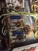
Thanks , I already used Dexoit on all the tube pins, sockets, switches jacks. And Faderlube on the control pots. I just recapped the phono stage .02uf and .022uf's. I used PIO .027uf for the .original Ceracap and .02 Musicap for the Black Ceramic .02. It did help alot , but the bottom end is a bit rolled off compared to the line stage only.
 

Attachments

  • IMG_7548.JPG
    IMG_7548.JPG
    73.6 KB · Views: 30
Thanks , I already used Dexoit on all the tube pins, sockets, switches jacks. And Faderlube on the control pots. I just recapped the phono stage .02uf and .022uf's. I used PIO .027uf for the .original Ceracap and .02 Musicap for the Black Ceramic .02. It did help alot , but the bottom end is a bit rolled off compared to the line stage only.
I am not a fan of using deoxit on tube pins and socket pins. I don't care what the product literature claims, the best contact between a tube pin and a socket pin is metal to metal. You might not realize that tubes operated perfectly fine for over 50 years before Deoxit showed up. Even the military did not use any kind of "contact enhancer". And they had all the money and the best scientists to find ways of obtaining the best environment or operating conditions for vacuum tubes. If there was a solution that made tubes conduct electricity better you can be sure the government would have used that stuff, especially if the fate of the free world depended on it.
The values of the resistors are important in the RIAA compensation curves. If you change out the resistors it might bring it back to where it should be. If this amp is going to be one you hang on to, i would splurge on some Takman carbon film resistors. But first measure the values of all carbon comps and see how far off spec they have drifted. If they are still within 5% you might have to start thinking about maybe getting a different phono stage or seeing if any different tubes helps.
 
Last edited:
I appreciate the replies.
I need to learn more about riaa phono stages and the different parts of the eq work.
I would like to keep this one, but I do need a decent phono stage.

I'll check the resistor values .

The line stage is sounding very good .

I've had very good results using deoxit on tube pins and sockets . I do not use it on faders or potentiometers as I have had it ruin one very expensive italian Icar pot.
But I respect your opinion.
 
Well, I did it or am doing it. I have disconnected the PEC filter 299 and it has made a world of difference for the better. Much more transparent, dynamic, everything is better. One problem, the gain is too high now. So too correct, I have paralleled a grid load resistor, I believe I have about 27k as opposed to the 1meg originally. I works well but now the input impedance is so low I needed to increase the input coupling cap to at least 0.1uf, 0.47uf was even better. So, Now I am comtemplating removing the cathode bypass cap (25uf) to lower the gain. Then readjust the grid load to something hopefully higher so I can use a smaller input cap.

I can tell you for certain it made a huge improvement and is now coming closer to my reference CJ PV12 and Premier 11a.

The Phono stage still needs works though I did make some improvement by increasing the coupling caps using just what ever I had, Polyester film Mallory 150's. I did notice the schematic seems to be backwards regarding the 100k plate and 270k plate as well as the corresponding cathode resistors. or maybe I am mistaken.
 
Update, I have completely removed and replaced the input cap .0015uf with a wire. The grid load is a 27k paralleled with the 2.2m and if I read the schematic right there is also a 1meg that became paralleled with that when I disconnected the PEC module. It is sounding fantastic, I never thought it could sound this good. Tone controls still function , I was going to bypass them with the scratch filter switch but no real need to at this point.
 
Back
Top Bottom