• The move to the new server is done. There are some software and database maintenance updates in process. This has us passing the hat around to help out. We appreciate any donations. Seriously, even a dollar helps. The payment page may be found here - https://www.audiokarma.org/support.html

AR "The Turntable" Restoration Musings

fidot

AK Subscriber
Subscriber
Howdy folks!

Well :)

An '85 AR The Turntable showed up at my doorstep about a week back. My intent is to clean it up; and replace my current Empire 498 with it - first, Empire needs a bit of TLC; and second, a certain gentleman associated with faint blue glow sometimes produced by tubes caused me to find out that these exist and be interested in them :).

I have been reading the main thread here; and thought that - wanting to focus on specific rework and areas that are covered amidst some posts deep in that, and branching threads, to make a new one and post my musings on the rework areas here. I hope I am not making a mess with this... I would've personally liked this kind of thread; so decided to do it.

So shall we?

The table was in decent condition and worked out of the box. Clapped out just enough to get exciting.

- Tonearm wobbly in both pivot directions
- Divot on the delrin disk at the bottom of the oil well
- A bit corroded platter; nothing bad
- Junk belt; of course
- Shot suspension (bent rods -- how?! - but then again; it shipped without the "lock screw")
- Pulley edges folded "up" in a couple places - someone tried removing it? :)

The plan is:

- Linn Basik (I tried tightening the tonearm; "left-right" bearing can't be fixed; it's just a metal rod in pot metal it seems; "up-down" can be tightened but still feels iffy; and I came across a Basik that was claimed to have been NOS for a reasonable amount, so that was a no brainer)
- ... on a hardwood base (rosewood or cocobolo, got both to try)
- main spindle/ball/thrust bearing cleaned up
- Vinyl Nirvana's springs; + mass balanced chassis
- Vinyl Nirvana's new pulley
- Motor cleaned up
- New belt
- New caps and tonearm cable because I can

And - as a later project - maybe replace the AC motor with the DC stepper motor
At any rate; first post is gonna be about the Hurst motor.

Should I name it Bluey... :) (*very* inside joke)
 
Register to hide this ad
Howdy folks!

Well :)

An '85 AR The Turntable showed up at my doorstep about a week back. My intent is to clean it up; and replace my current Empire 498 with it - first, Empire needs a bit of TLC; and second, a certain gentleman associated with faint blue glow sometimes produced by tubes caused me to find out that these exist and be interested in them :).

I have been reading the main thread here; and thought that - wanting to focus on specific rework and areas that are covered amidst some posts deep in that, and branching threads, to make a new one and post my musings on the rework areas here. I hope I am not making a mess with this... I would've personally liked this kind of thread; so decided to do it.

So shall we?

The table was in decent condition and worked out of the box. Clapped out just enough to get exciting.

- Tonearm wobbly in both pivot directions
- Divot on the delrin disk at the bottom of the oil well
- A bit corroded platter; nothing bad
- Junk belt; of course
- Shot suspension (bent rods -- how?! - but then again; it shipped without the "lock screw")
- Pulley edges folded "up" in a couple places - someone tried removing it? :)

The plan is:

- Linn Basik (I tried tightening the tonearm; "left-right" bearing can't be fixed; it's just a metal rod in pot metal it seems; "up-down" can be tightened but still feels iffy; and I came across a Basik that was claimed to have been NOS for a reasonable amount, so that was a no brainer)
- ... on a hardwood base (rosewood or cocobolo, got both to try)
- main spindle/ball/thrust bearing cleaned up
- Vinyl Nirvana's springs; + mass balanced chassis
- Vinyl Nirvana's new pulley
- Motor cleaned up
- New belt
- New caps and tonearm cable because I can

And - as a later project - maybe replace the AC motor with the DC stepper motor
At any rate; first post is gonna be about the Hurst motor.

Should I name it Bluey... :) (*very* inside joke)
There was, years ago, a member @ AK who was among the most highly-regarded AR restoration and modification specialists in the world. I acquired an AR The Turntable from him, a restored (perfectly) (George) Merrill Modified The Turntable. The thing was magnificent and though the first cart was (vintage) Shure V-15 IV, I switched to (also vintage) Shure V-15 III ... just preferred the sound through the Type III.

So, I don't know if "Dave" is still a member here, but his website is up and going strong:

https://vinylnirvana.com/

Enjoy the Youtube video he's embedded. Yes, that is Dave.

Note he also restores Thorens tables.

Good luck in your restoration.
 
Musings on the Hurst Motor

I know that one of the typical procedures for the motor is to pull the pulley with two spoons as levers, put a drop of oil on the shaft near the motor bushing, and have it spin for a long time. Then add some more oil. "Tighten it up" until there's no / very little play by gently hammering down the press on stopper. Etc.

If I may offer a bit of commentary...

But first; let's look at the motor. Sorry, this is not to scale :).

Motor.Crosssection.jpeg

When you pull the pulley, you will see the "press on stopper" and the top of the top "bushing". You won't see the "thrust washer" - it's smaller in OD that the stopper.

It's actually very clever. It's running in two bushings, with no bearing on the opposite end at all. Magnet is a "cup", hiding the long housing for the run bushings.

Over the years; the motor gets dirty; and whatever lubricant was in there gets stale. Best is to clean all that out. When it's run with a drop of oil placed into the top; that will eventually drain into the "cupped" magnet - especially if too much oil is put on. Then, it may throw off the cup's balance, collect more dirt, etc. Maybe I'm overthinking things...

I decided to take it apart - which is a reverse process of "tightening" up (by mildly hammering the stopper down).

Light taps with a 4oz hammer on the shaft, while holding the motor in my cupped hand (and with back cover taken off of course):

Motor.Bushing.Up.jpeg

... find the right (brass!) punch, and finish the job.
Motor.Disassembled.jpeg

You can see the shaft / magnet, press on stopper, and thrust washer here.

Now, this can be properly cleaned. This requires a smoking pipe (tobacco!!), good weather, good tobacco, good pipe cleaners, and a solvent (I used alcohol).

- Put the pipe cleaner into the bushings
- Drop alcohol on it (so that it becomes soaked inside)
- Pack a pipe, go outside, and smoke it (~30-45 minutes)
- Use pipe cleaners to clean the pipe
- Go back inside, pull the soaked and now black (!) pipe cleaner out of the bushing
- Repeat, until pipe cleaners coming out are completely pristine

See, you're supporting two hobbies at the same time now! - and also, you are making sure that - if these *were* oil-impregnated bushings - that you will pull all the old stuff out of them

Now, let it dry overnite.

Next comes the question of lube. Given that what's coming out as the process above is yellow and "oily", it might have been indeed oil impregnated bushings. It also might have been greased - do you see that space in between top and bottom bushings on my diagram? That could've had grease.

I do not know; and greasing would plug the pores on the bushing if it's supposed to be oil impregnated, so I decided to oil and monitor. If it needs more oil later, it's probably not oil impregnated :).

What I did was stick a pipe cleaner in there, soak it with oil, and leave that overnite.

Then, I cleaned it out again (mainly off of possible pipe cleaner fluff) - but without soaking! - and *then*, let it run in, *upside down* - with no collar and thrust washer - adding oil periodically (and letting it drip down and out and not fouling the magnet cup). In fact, it's running right now as I am typing this.

I heard somewhere that the legendary Mr. Marc Morin used to run these motors inside an oil bath "pod". That sounds very clever! It completely resolves the lubrication problem; and maybe dampens some vibrations that are happening when the motor runs (just run it in your hand while it's removed from the top plate and you'll know what I'm talking about).

--

Couple final words. The motor can still be bought from Hurst, direct; here: https://www.hurst-motors.com/aabdirectdrive.html

Or, if you want a sub-project - and I am considering to do it later - there's a DC stepper variety, model 3007-001, https://www.hurst-motors.com/asabsdirectdrive.html, which seems to fit perfect. I can imagine a little built in speed controller with 2 fine adjust pots, and a 3-position toggle - "45", "33", and "off". Right where the old rocker switch is; with pots maybe screwdriver-adjustable types hidden somewhere... This way you will never need to flip the belt to the big side of the pulley too. I wonder if this is what was done on TTs where there was an external speed control box.... I have seen it somewhere...
 
...
So, I don't know if "Dave" is still a member here, but his website is up and going strong:
https://vinylnirvana.com/

....

Good luck in your restoration.

Thank you! I did spend an hour talking to Mr. Dave yesterday. :)

Meanwhile;

Platter / Shaft / Shaft Well / Thrust Plate Musings

Next were the main bearing - the heart of the mechanics - the shaft of the platter and the platter itself.

First of, filling the well with brake cleaner and draining it a few times totally works - it gets all the oil out, and the thrust bearings (white delrin disks) can be knocked out by gently tapping the well upside down on a chunk of 2x4.

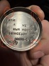
Pleasant surprise! I didn't know AR included spares!

Spindle.Delrin.Disks.jpeg

Bottom one is the worn one. I have 2 more to go thru!

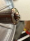
Next, the ball. Here's what we're dealing with.

Ball.Shot.jpeg


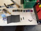
And here's the arrangement of ... tools (just abrasives; exclude file/file card/mallet/screw'check'r/green box/sharpie/etc) ?


Ball.Abrasives.jpeg


400 -> 800 and an array of MicroMesh pads from 1500 to 12000.

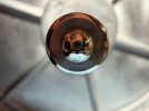
You will see a picture of the tool I used to spin the spindle in a second; but meanwhile:

Ball.Finished.jpeg


Yes, there's some pitting on the side still. I did not bother with that; it's way up the ball's contact area.

Next, the platters themselves.

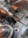
If this is not in the book of "stupidest setups ever", it should be.
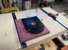
Crazy.Setup.jpeg


You see, it's a ton easier to do all this polishing, sanding, etc when the piece you're polishing and sanding is nicely affixed to 1500+lbs of heavy iron right in front of you.

There are these tools that are quality of life tools. Your first multimeter. Your first scope. Your first Hakko. Your first electric drill, compressor, lathe. Lathes needs to be available to every workshop.

I used Scotch Brite and (WD40) on the platters surfaces, edges. Cosmetic areas got to grey. Contact areas (belt / top) I used maroon only not to make them any smoother; for gription (similar, but different, from "stiction").

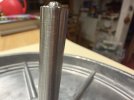
Meanwhile, the last remaining portion was the shaft. I read in the "big thread" Marc Morin's post about cross-hatching with 400 followed by 1500 (wet! - I used WD40, the "universal machine shop cutting oil").

Never done it. Took a bit of practice (on scrap). Making "spirals" instead of just "sanding" takes a bit of getting used to. Ideally, I would probably use some tooling setup in a toolholder to hold the paper; and lathe's autofeed for perfect consistency, but I wasn't in the mood for building a tool.

Here's the end result:
Shaft.Crosshatch.jpeg

I didn't cross hatch the well. Read Marc's post about it being lead babbit; and was scared to mess it up (soft, remove too much, smear, ...). Additionally, I can't imagine precise ID sanding with that diameter ID...

Instead, I ran a strip of Scotch Brite chucked into my drill in and out of the well, and called it a day. Just to lightly scrub off the dirt.

If someone here knows the process, would be great to hear some advice.

Meanwhile, I couldn't wait. Cleaned it up and put together, spun up with my finger to ~33RPM, and let it ride. 2 minutes and change! I think this isn't too bad? :).

--

More random thoughts.

What about statically balancing the platter (the whole piece; together; obviously they will have to be marked so that they are always reassembled with proper clocking between outer and inner)? I can imagine a setup with a surface plate, v-blocks.. maybe a reamed bushing.. maybe the sub chassis itself - turned 90 degrees...?

When polishing the shaft, noticed that the "tit" - the little pin that the records goes on - is not concentric with the rest of the thing. I held the subplate by that "tit" in the collet - yes, there is runout in the collet but not THAT much - it was weeble-wobbling pretty good. Holding it by the shaft runs "perfectly" (nothing is perfect of course). The "tit" should have been machined as a part of the whole thing, making it concentric with the rest of the arrangement...

What about *dynamically* balancing it after balancing it statically...? Ie; this: https://www.emachineshop.com/dynamic-flywheel-balancing/
 
Thank you! I did spend an hour talking to Mr. Dave yesterday. :)

Meanwhile;

Platter / Shaft / Shaft Well / Thrust Plate Musings

Next were the main bearing - the heart of the mechanics - the shaft of the platter and the platter itself.

First of, filling the well with brake cleaner and draining it a few times totally works - it gets all the oil out, and the thrust bearings (white delrin disks) can be knocked out by gently tapping the well upside down on a chunk of 2x4.

Pleasant surprise! I didn't know AR included spares!

View attachment 3637580

Bottom one is the worn one. I have 2 more to go thru!

Next, the ball. Here's what we're dealing with.

View attachment 3637581


And here's the arrangement of ... tools (just abrasives; exclude file/file card/mallet/screw'check'r/green box/sharpie/etc) ?


View attachment 3637582


400 -> 800 and an array of MicroMesh pads from 1500 to 12000.

You will see a picture of the tool I used to spin the spindle in a second; but meanwhile:

View attachment 3637583


Yes, there's some pitting on the side still. I did not bother with that; it's way up the ball's contact area.

Next, the platters themselves.

If this is not in the book of "stupidest setups ever", it should be.
View attachment 3637586


You see, it's a ton easier to do all this polishing, sanding, etc when the piece you're polishing and sanding is nicely affixed to 1500+lbs of heavy iron right in front of you.

There are these tools that are quality of life tools. Your first multimeter. Your first scope. Your first Hakko. Your first electric drill, compressor, lathe. Lathes needs to be available to every workshop.

I used Scotch Brite and (WD40) on the platters surfaces, edges. Cosmetic areas got to grey. Contact areas (belt / top) I used maroon only not to make them any smoother; for gription (similar, but different, from "stiction").

Meanwhile, the last remaining portion was the shaft. I read in the "big thread" Marc Morin's post about cross-hatching with 400 followed by 1500 (wet! - I used WD40, the "universal machine shop cutting oil").

Never done it. Took a bit of practice (on scrap). Making "spirals" instead of just "sanding" takes a bit of getting used to. Ideally, I would probably use some tooling setup in a toolholder to hold the paper; and lathe's autofeed for perfect consistency, but I wasn't in the mood for building a tool.

Here's the end result:
View attachment 3637590

I didn't cross hatch the well. Read Marc's post about it being lead babbit; and was scared to mess it up (soft, remove too much, smear, ...). Additionally, I can't imagine precise ID sanding with that diameter ID...

Instead, I ran a strip of Scotch Brite chucked into my drill in and out of the well, and called it a day. Just to lightly scrub off the dirt.

If someone here knows the process, would be great to hear some advice.

Meanwhile, I couldn't wait. Cleaned it up and put together, spun up with my finger to ~33RPM, and let it ride. 2 minutes and change! I think this isn't too bad? :).

--

More random thoughts.

What about statically balancing the platter (the whole piece; together; obviously they will have to be marked so that they are always reassembled with proper clocking between outer and inner)? I can imagine a setup with a surface plate, v-blocks.. maybe a reamed bushing.. maybe the sub chassis itself - turned 90 degrees...?

When polishing the shaft, noticed that the "tit" - the little pin that the records goes on - is not concentric with the rest of the thing. I held the subplate by that "tit" in the collet - yes, there is runout in the collet but not THAT much - it was weeble-wobbling pretty good. Holding it by the shaft runs "perfectly" (nothing is perfect of course). The "tit" should have been machined as a part of the whole thing, making it concentric with the rest of the arrangement...

What about *dynamically* balancing it after balancing it statically...? Ie; this: https://www.emachineshop.com/dynamic-flywheel-balancing/
Beautiful work and glad you touched base with Dave, he's not only a font of information, he also has LOTS OF PARTS for AR (and Thorens) restorations.
 
Musings on the Hurst Motor

I know that one of the typical procedures for the motor is to pull the pulley with two spoons as levers, put a drop of oil on the shaft near the motor bushing, and have it spin for a long time. Then add some more oil. "Tighten it up" until there's no / very little play by gently hammering down the press on stopper. Etc.

If I may offer a bit of commentary...

But first; let's look at the motor. Sorry, this is not to scale :).

View attachment 3637573

When you pull the pulley, you will see the "press on stopper" and the top of the top "bushing". You won't see the "thrust washer" - it's smaller in OD that the stopper.

It's actually very clever. It's running in two bushings, with no bearing on the opposite end at all. Magnet is a "cup", hiding the long housing for the run bushings.

Over the years; the motor gets dirty; and whatever lubricant was in there gets stale. Best is to clean all that out. When it's run with a drop of oil placed into the top; that will eventually drain into the "cupped" magnet - especially if too much oil is put on. Then, it may throw off the cup's balance, collect more dirt, etc. Maybe I'm overthinking things...

I decided to take it apart - which is a reverse process of "tightening" up (by mildly hammering the stopper down).

Light taps with a 4oz hammer on the shaft, while holding the motor in my cupped hand (and with back cover taken off of course):

View attachment 3637577

... find the right (brass!) punch, and finish the job.
View attachment 3637578

You can see the shaft / magnet, press on stopper, and thrust washer here.

Now, this can be properly cleaned. This requires a smoking pipe (tobacco!!), good weather, good tobacco, good pipe cleaners, and a solvent (I used alcohol).

- Put the pipe cleaner into the bushings
- Drop alcohol on it (so that it becomes soaked inside)
- Pack a pipe, go outside, and smoke it (~30-45 minutes)
- Use pipe cleaners to clean the pipe
- Go back inside, pull the soaked and now black (!) pipe cleaner out of the bushing
- Repeat, until pipe cleaners coming out are completely pristine

See, you're supporting two hobbies at the same time now! - and also, you are making sure that - if these *were* oil-impregnated bushings - that you will pull all the old stuff out of them

Now, let it dry overnite.

Next comes the question of lube. Given that what's coming out as the process above is yellow and "oily", it might have been indeed oil impregnated bushings. It also might have been greased - do you see that space in between top and bottom bushings on my diagram? That could've had grease.

I do not know; and greasing would plug the pores on the bushing if it's supposed to be oil impregnated, so I decided to oil and monitor. If it needs more oil later, it's probably not oil impregnated :).

What I did was stick a pipe cleaner in there, soak it with oil, and leave that overnite.

Then, I cleaned it out again (mainly off of possible pipe cleaner fluff) - but without soaking! - and *then*, let it run in, *upside down* - with no collar and thrust washer - adding oil periodically (and letting it drip down and out and not fouling the magnet cup). In fact, it's running right now as I am typing this.

I heard somewhere that the legendary Mr. Marc Morin used to run these motors inside an oil bath "pod". That sounds very clever! It completely resolves the lubrication problem; and maybe dampens some vibrations that are happening when the motor runs (just run it in your hand while it's removed from the top plate and you'll know what I'm talking about).

--

Couple final words. The motor can still be bought from Hurst, direct; here: https://www.hurst-motors.com/aabdirectdrive.html

Or, if you want a sub-project - and I am considering to do it later - there's a DC stepper variety, model 3007-001, https://www.hurst-motors.com/asabsdirectdrive.html, which seems to fit perfect. I can imagine a little built in speed controller with 2 fine adjust pots, and a 3-position toggle - "45", "33", and "off". Right where the old rocker switch is; with pots maybe screwdriver-adjustable types hidden somewhere... This way you will never need to flip the belt to the big side of the pulley too. I wonder if this is what was done on TTs where there was an external speed control box.... I have seen it somewhere...
Pretty standard Hurst motor there. How did you remove the rear cap?
 
... while waiting for the tonearm, and to make the tonearm board -

Plinth Musings.

Not doing anything special; but the feet are both petrified; and falling out of loose holes in crumbly corner blocks' MDF.

Feet can be had from our friends at McMaster-Carr (part #9540K911, https://www.mcmaster.com/9540K911/).

For the holes / corner blocks, employed my old trick I used on loose hinge holes in doors (like, your regular house doors).

Stuff the hole with toothpicks covered in wood glue:

hole.toothpicks.jpeg


Clamp the ones that were cracked:

hole.clamped.jpeg


Now; don't let the glue dry 100% and become hard as a rock! "Rubbery" condition. ~4-6 hours?

Then, cut it flush with an appropriately dull (or sharp, if you're not as lazy as me) chisel:

toothpicks.cut.jpeg

Then, drill real careful (you're drilling into end grain of toothpicks basically; which is the nastiest drilling job). I usually use a guide; or, here, I very carefully started with 1/16th bit and then went to full size.

Done!

hole.drilled.jpeg

Done! Holes are tight again.

note to self: fix the Strat's strap button hole in the same manner....
 
Well, before we can start figuring out the springy parts, we need a tonearm to attach to the subchassis... and before doing so, we need a tonearm "plate". So,

Tonearm Subplate Musings.

Of course we're gonna replace the tonearm subplate :). We can do better than MDF!

Reading various topics; it seems that Mr. Marc Morin was going for matching hardness / density / vibration characteristics of the tonearm subplate - idea being; if sub-chassis shakes; and transmits those shakes to the tonearm via the tonearm subplate in exactly the same manner, then the tonearm and the platter (and therefore the actual record) shaking in the same manner makes *relative* shaking of record to needle equal to 0. "Complete Loop" is I think the term I read? Not an engineer; my backyard mechanic brain though could best explain this in the manner above....

To achieve that, hard (very hard!) woods apparently had to be used. I remember cocobolo (because "cocobolo desk" - yes, a particular TV show reference here!). So, to local friendly Rockler I went.

They didn't have cocobolo. Well shucks. But a very helpful gentleman pointed me to the relative hardness chart they had next to the wood stack, and we started looking for hardnessess "in the ballpark" around cocobolo. I also wanted as flat a boards as possible - grain structure on many good specimens was such that they were warped and resembled blanks of airplane props :(.

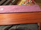
At any rate, that yielded 2 boards. A Paduk board; and a Purpleheart board.

1764222214390.jpeg

My woodshop's all packed up (long story); so I was to pay a visit to a friend.

First, we match drill the holes - and use those to attach the old plate (that was to be a pattern) to the board.

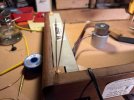
1764222271857.jpeg

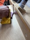
Then, a quick pencil contour, and hack off most of it on a scroll saw

1764222297790.jpeg

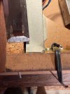
Pattern bit in a router next, and we have our basic shape!

1764222338048.jpeg

Next, comes the drilling for the tonearm.

We know the overhang and the arm effective length. Latter less former yields spindle centerpoint to arm centerpoint distance; and I managed to find a drilling template for my tonearm online (though making one would be trivial too - it's just concentric circles; one for the "main" hole and a hole circle for mounting screws).

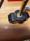
Once we know the distance, we need to mark it.. somehow... What I did was attach the arm plate to the sub-chassis, and stick an appropriate diameter gauge pin into the spindle well. My total distance then would be "Effective length + 1/2 diameter of the gauge pin". Minor imperfections are okay; that will be adjusted later at the headshell.

1764222598148.png

We mark the centerpoint at the intersection of my caliper jaw; and the centerline of the plate.

1764222653405.png

Look carefully - see that little needle hole in the wood? That's the center point. Also, see my neat trick? I flipped the wood species on ya! Yep; I am making two :).

Next, the rest of the holes. Position the template properly by rotating it around the centerpoint to line up it's centerline:

1764222741083.png

Pin (centerpuch) the three mounting holes; and we're off to the drillpress!

1764222824125.jpeg

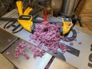
... there's the actual piece of wood buried under all those chips.. somewhere...

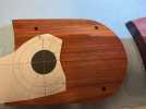
Then, just a little sanding, and a little tung oil (mixed 5050 with Mineral Spirits), and the plates are done!

1764222868859.jpeg
 
Well, before we can start figuring out the springy parts, we need a tonearm to attach to the subchassis... and before doing so, we need a tonearm "plate". So,

Tonearm Subplate Musings.

Of course we're gonna replace the tonearm subplate :). We can do better than MDF!

Reading various topics; it seems that Mr. Marc Morin was going for matching hardness / density / vibration characteristics of the tonearm subplate - idea being; if sub-chassis shakes; and transmits those shakes to the tonearm via the tonearm subplate in exactly the same manner, then the tonearm and the platter (and therefore the actual record) shaking in the same manner makes *relative* shaking of record to needle equal to 0. "Complete Loop" is I think the term I read? Not an engineer; my backyard mechanic brain though could best explain this in the manner above....

To achieve that, hard (very hard!) woods apparently had to be used. I remember cocobolo (because "cocobolo desk" - yes, a particular TV show reference here!). So, to local friendly Rockler I went.

They didn't have cocobolo. Well shucks. But a very helpful gentleman pointed me to the relative hardness chart they had next to the wood stack, and we started looking for hardnessess "in the ballpark" around cocobolo. I also wanted as flat a boards as possible - grain structure on many good specimens was such that they were warped and resembled blanks of airplane props :(.

At any rate, that yielded 2 boards. A Paduk board; and a Purpleheart board.

View attachment 3642324

My woodshop's all packed up (long story); so I was to pay a visit to a friend.

First, we match drill the holes - and use those to attach the old plate (that was to be a pattern) to the board.

View attachment 3642325

Then, a quick pencil contour, and hack off most of it on a scroll saw

View attachment 3642326

Pattern bit in a router next, and we have our basic shape!

View attachment 3642327

Next, comes the drilling for the tonearm.

We know the overhang and the arm effective length. Latter less former yields spindle centerpoint to arm centerpoint distance; and I managed to find a drilling template for my tonearm online (though making one would be trivial too - it's just concentric circles; one for the "main" hole and a hole circle for mounting screws).

Once we know the distance, we need to mark it.. somehow... What I did was attach the arm plate to the sub-chassis, and stick an appropriate diameter gauge pin into the spindle well. My total distance then would be "Effective length + 1/2 diameter of the gauge pin". Minor imperfections are okay; that will be adjusted later at the headshell.

View attachment 3642329

We mark the centerpoint at the intersection of my caliper jaw; and the centerline of the plate.

View attachment 3642330

Look carefully - see that little needle hole in the wood? That's the center point. Also, see my neat trick? I flipped the wood species on ya! Yep; I am making two :).

Next, the rest of the holes. Position the template properly by rotating it around the centerpoint to line up it's centerline:

View attachment 3642331

Pin (centerpuch) the three mounting holes; and we're off to the drillpress!

View attachment 3642332

... there's the actual piece of wood buried under all those chips.. somewhere...

Then, just a little sanding, and a little tung oil (mixed 5050 with Mineral Spirits), and the plates are done!

View attachment 3642333
Your AR "TT" restoration project is coming along very well.
 
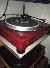
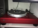
This is mine after a complete rebuild, contact me for more info on what I did.

Very nice!

Looks like you stripped the top aluminum plate besides refinishing the plith. Looks like the original tonearm.

What is that fancy roller like thingie? Record cleaner? Does it work well? What is it precisely - brand / model / part # if you don't mind - assuming it works well? I was looking at "autocleaners" for a while and it seems the biggest complaint about them is they're kinda gimmicky.

And yes; it would be lovely to know what you did!
 
The original tonearm that came with it had slop in both pivot bearings... and while the pivot vertical slop could've been fixed by tightening, the horizontal pivot slop based on cursory study, could not - not easily at least. Nope; and my following actions have nothing to do with me maybe possibly messing up one of the pivot needles! :)

I was idly looking for a Linn Basik LVX - and one just popped up on an auction site as "never installed", with the guy agreeing to a very reasonable price to boot! I decided to go with that. Never installed, new tonearm will just work out of the box. Right? Well, with a bit of cleanup maybe.

Thusly; we arrive at

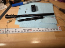
The Linn Basik LVX Musings - part 1 - aka A Bucket of Goofs

Never installed. Ha! Of course it was installed. I see all kinds of marks showing cartridge mounting hardware marks on it, signs of it having been adjusted, and such and such. The horizontal pivot had no slop, vertical pivot had slop, but it had the same needles as the AR arm - and with slotted lock nuts, would've been easy to work on without making special tools to remove those nuts.

We came to an amicable resolution with the seller, and on I went.

Let's look at those pivots and bearings?

ta.pivot.pin.jpg

Do you see that "used" groove on the pin?

ta.pivot.balls.jpg


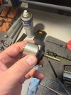
Those white spots on the balls isn't dust: it doesn't blow off. It washes off though (I used spray contact cleaner).

Okay, so up down pivots, we have our work cut out for us.

Intermission: Removal of Fasteners on That Tonearm.

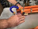
They are all threadlocked in place - well, most of them are. Heat is your friend! I use my hand torch with the "heatgun" nozzle on it - same setup I use to shrink the heatshrink. Beauty is, there's no direct flame touching anything, and you can control the heat very very well.

ta.torch.jpg

Now... though it softens the threadlocker, it doesn't remove it from the threads, which means there's still some torque required to get them out... and - on the second pin - I was too ginger with the torch and too much of a 300-lb gorilla with the torque.... :( Damn it!

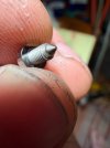
ta.screw.slot.jpg

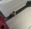
It's a slotted pin, right? 1/2 of the side just snapped off :( Oh well. A bit of filing will solve this. The pin is extra long, so we should be fine.

Analyzing this screw-up, the lesson I learned is, don't worry much about the heat! Wires are super far away from most of these spots, there's lots of aluminum around to soak up the heat. Make sure the thing is properly warm and moving easily - if, while unscrewing, resistance increases beyond comfortable, don't force it - heat up some more!

Now that is not to say that you should get this blazing hot either. Use common sense. Heat a little, try to move it. Heat a little more, try to move it. I applied this technique to the rest of the threadlocked fasteners I removed - including much nastier allen head set screws with a much less resistance to stripping - with good results.

Anyway, back to it.

--

... but if the up/down pivot bearings are in this sad a state, then the horizontal pivot bearing might be sad as well?

Let's take this apart a little more.

A couple more set screws reveal this.

ta.antiskate.jpg

Aha! Now I know how this antiskate works. The white "arm" touches the pin in the pivoting yoke, and you control the tension on the spring on the left with the "wind-up wheel" that adjusts anti-skate. Nice :)

And now, we also see the main bearing. Let's take this anti-skate bit off so that we have better access; and try it, shall we?

.... it's very very bad:


I don't know about you guys; but in my book this bearing is. Shot.

There's a nut on the top. To go further, I need to fish the wires out of the tube - and in fact remove the whole arm, leaving just the "yoke". But I don't want to desolder those tiny wires!!! :(. Damn man. I was gonna just buy myself a tonearm, throw it on, and call that a day...

What am I getting into... :(

Oh well.

Connector desoldered, and nut removed.

Bearing!!!

ta.balls.jpg

Okay, I see what's going on now. The nut is also a race, and tightening it sets preload / tension on the bearing. The other side has the same balls as well, but the yoke itself has the race surface on it (we'll see it in a bit).

Let's look at the nut's race surface:

ta.race.jpg

Nope, not good at all. We can do way way better! It's the nut's "flat" - and maybe a bit of that ID chamfer - that act as a race here.
I'll spare you the pictures of mating races on the shiny barrel piece - they're about the same level of crunchiness.
All that goes on the "to polish" list.

Oh, and the yoke:

ta.yoke.pin.jpg

The pin for anti-skate is removable with heat as well. No worries there!

One more final thing to consider.. is maybe trying to get some fancier balls? No! This has nothing to do with me having an odd number of them (and hence possibly having misplaced one? Or three? Or...?)

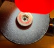
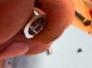
No, seriously though - if you do this - be very careful! When I loosened the nut, I noticed the balls in there before they spilled. Tightened it back, and got that little red box container in the picture to "drain" them. What I didn't realize is how bouncy they would be - which spelled my doom. If I was to do that again, I would do that in a container with super tall walls, or flooded the bearing with oil first to make the balls sticky.... Or both. It seems to me that it "wants" 20 balls per side (I have 39 balls).

Diameter of the balls are 0.0149 according to my mike. About half a diameter of a mustard seed. Be careful! << NOTE added later: this is incorrect, they're .039 (1mm); I am a dufus. More notes in the future post :)

My current thinking on the ball diameters is: the actual diameter is not that important, because the races are conical. They will accept similar sized balls with no problems. Smallest ones I was able to order were 0.4 mm (0.0157) and 0.5mm (0.0196). We'll see. I will post the ones I end up using along with the vendor I used once I get some results.
 
Last edited:
The Linn Basik LVX Musings - part 2

To the shop!

Let's polish some races and pins - and fix that buggered up slot in one of the pins?

We'll with that pin in fact. I chucked it and cut off the still remaining 1/2 (as little as I can; I am not trying to make it pretty); and then used a tiny file for guitar nuts to re-slot it. Followed up with a proper sized die to clean up the threads.

ta.slot.fixed.jpg

Next, to polishing.

That yoke.. that'll be hard to hold in the lathe. Yes, I can chuck it, but I didn't want to put pressure on it's "ears". After mulling over and brooding for about a half hour, realized that.. a hole thru it looks suspiciously like a hole just right for tapping a #6 thread! We will assimilate this tonearm after all - what is this... metric threads on an American-made turntable -- nonsense!

ta.yoke.threads.jpg

You say, "but wires will go thru it! those threads are sharp, you will cut them!"

I'll say, "that's a problem for tomorrow me. I can polish them to round over the crests; I can drill them off. I can fill the thing with epoxy and re-drill it back to the correct ID". For now, these threads are critical, and for a reason I didn't expect.

Now, to the holding mandrel.

ta.mandrel.jpg


ta.mandrel.done.jpg

Do you see what's happening there? #6 screw thru a threaded hole in an aluminum "puck", pokes out and I can then thread on the yoke. I can chuck the "puck" in a collet, and go at it.

But wait. Why is there such a massive wobble at the tip of the tube when I spin this....? Oh no...

It's bent. That brass tube - that defines the relative position of 2 bearings to one another - is bent... ~0.015 runout at the tip. That's 3 times worse than my very first crappy cheapo Chinesium drill press! That will not do. I am wondering how the hell that could've happened..... I am now having a *strong* suspicion that someone else was inside this arm. See those marks on the brass tube in the picture above - like if someone tried to hold it with Channelock pliers? That was NOT me. No, no joke, that was not me. Well, ugh :(

Here's how I measured this.


... and then, it was a tedious "adjust, bend, adjust" cycle. I used a parallel plier type deal in the end to hold the shaft at the tip and bend it. I think it worked!


Why did I not try to go better?
Well. To be honest, I do not trust myself enough to attempt a better / cleaner setup while being sure I am not "chasing my own tail" because of inaccurate measurements, not very rigid dial indicator stands, not very rigid and pretty clapped out lathe, etc. I think I have improved it - from ~15 down to ~2 thou. 7 times.

For now, I will leave this alone. When the balls show up, we'll reassemble and try.

I also have this "commonsensical" thought that because the top race is a part of the nut that's screwed on, and threads have slop in them that is way greater than 2 thou - they have to be! - it will "self align". The actual critical surfaces that determine relative positioning are on the "barrel" that goes over the yoke's shaft tube. The tube has to be straight.. enough.

Or maybe, I am rationalizing :)
 
Random Friday Night Musings

I got bogged down with waiting for bearings, waiting for other stuff, realizing that what I described above about the pivot bearing is not entirely correct... I'll post an update, I promise..

Meanwhile, couple of brooding thoughts.

I don't like Linn's jenky headshell side connections... Should I "hardwire" or solder them? Got an ADC LMH-1 headshell from LP Gear (should have the same headshell side connector) to compare; maybe will replace Linn's headshell connector with that one (mine has corrosion, may be tired, etc)... Any opinions?

Damn, it would be nice to find some threads here of folks replacing bearings! Those vertical pivot ones. I am finding breadcrumbs from Big Bill; and Marc Morin mentioning sapphires (for a different tonearm; but hey - they can be adopted here as well!). If only I could figure out how to get the old vertical pivot bearings out of that tonearm block.... I tried heat, clamping them in a collet and pulling / gently twisting, I don't want to go 300LB gorilla on them or do anything destructive (like welding a puller to the race.. hehe :)).

Rewire. Let's title the following picture, "I am not yet committed to my tonearm rewire!":

1764989666693.png

... fine, I did order some KAB wires :) I really wanted these: https://www.trans-fi.com/p/shop_18.html but the guy seems to be out of business?

And finally, this. I can watch this on a loop for an hour :) This is my first approximation of jounce :)

 
I am loving this thread... I have the exact same table that I am enjoying right now and wanting to update this winter. Is that video with the new springs? BEAUTIFUL BOUNCE!

Also in the video is the platter mass loaded?

I get stereophile/absolute sound in the mail but this thread (with pictures) has been more interesting than anything I've read in those magazine lately.

Thanks for taking the time to share!
 
I am loving this thread... I have the exact same table that I am enjoying right now and wanting to update this winter. Is that video with the new springs? BEAUTIFUL BOUNCE!

Also in the video is the platter mass loaded?
…skip

Thank you!

These are new springs from Vinyl Nirvana; and yes, the base has some weights on it. This was my first approximation of how much it’ll need - if you look carefully you’ll see stacks of wheel weights loosely positioned. Without that, the resting state is very crooked… that post is still in the future; I’m about 1/3 way towards finishing the sub chassis weighing, but got bogged down with the Tonearm stuff (and I need the Tonearm to be there to finish the sub chassis tuning).
 
Awesome! There are so man bread crumbs scattered by Marc and those who worked with him. I look forward to your post on adding mass to the sub chassis as I plan to update the springs this winter. You inspired me to flip the delrin thrust pad this morning :music:
 
Back
Top Bottom