• The move to the new server is done. There are some software and database maintenance updates in process. This has us passing the hat around to help out. We appreciate any donations. Seriously, even a dollar helps. The payment page may be found here - https://www.audiokarma.org/support.html

AR "The Turntable" Restoration Musings

The Linn Basik LVX Musings - part 3: The Bearing Blues.

So this was quite a hiatus... Lots of other stuff (fixed voltage regulator on the old FJ43!), and lots and lots of noodling and failing.

We left our tonearm disassembled, with me having a list of things to polish, lost bearing balls, and a desire to upgrade them.

I also made quite a few mistakes in the Linn Part 2 Musings, which I intend to correct here.

Let's start with the bearing diagram...

1766292172120.png

This is sideways, with the bottom being on the right side of the picture. Not to scale! :).

Somewhere in the Part 2, I believe in one of the videos, I said that the perfect straightness of the brass tube (red piece on the diagram) is not that important. Well, that was mistake number one: it is! It's obvious from the diagram. Each bearing race is made out of three surfaces: a flat on the yoke or the tension nut, the tapers on the end of the fixed cylinder, and the brass tube itself.

Mistake number two, by the way, was the ball size. Ordered some "slightly bigger" (0.5mm balls - I measured approx. 0.4mm). They came, and I immediately realized they were too small. What the...?

I measured the originals as 0.014. The actual diameter of the originals was 0.039. Which happens to be 1mm!! Now that's a round number and makes a ton more sense. Those of you who ever used a micrometer should be laughing at me at this point :) (hint: 0.039 - 0.014 = .025). Yeah. Dumba$$.

Well, 1mm bearing balls is a lot easier to find. I ultimately had a choice - stainless steel balls of pretty low grade (G25 if I recall right) from McMaster-Carr (whom I can trust), ceramic balls from VXB Bearings with no grade listed, or ceramic balls listed as G5 (a very nice grade!) from skiffmadeblades.com (seems like a knife shop). I decided to go with Skiff.

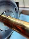
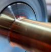
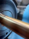
Meanwhile, once I realized the brass tube was integral to concentricity and everything, I decided to machine it in situ along with the yoke side race. That would make them perfectly concentric and perpendicular. Yes, my lathe is clapped out and cuts tapers (meaning that OD of the brass tube will be smaller by a few thousandths on one side than the other); but that's no problem here: ball's contact area is a point, so as long as we're all concentric and square, we should be fine.

That lead me to trying to make a jig, re-measuring, finding problems, measuring again, realizing that the most important part in the concentricity equation is the relationship of the "ears" of the yoke to the pivot.

It's much easier to explain when showing, so here:


And a bit of the results of the final straightening:


Did I say I wasn't gonna machine it? :) Well, I did in the end.

bearings.02.machining.jpg

... using my "puck with the screw" I described in part 2 and was so afraid would cause issues. It didn't.

One of the reasons I ended up deciding to machine was to get rid of the "divots" and pits on the flat race on the yoke, and start fresh.

Oh - I didn't mention the divots?

bearings.01.divots.jpg

This is what we're dealing with guys. Those little "holes" dug by the balls over time is what is causing the rumbling noise when the thing spins; each ball has to roll "in" and "out" of the hole. How do I know? :) Well... we'll get there. Let's say I staged an experiment to convince me.

I took off just a hair - just a couple thousandths - to make a clean new surface, and went to polishing.

Shoulder polishing, and ID polishing of the "fixed cylinder"'s race areas (remember the diagram?) took a lot of figuring out. What I learned is you can't skimp and rush, you have to have really good and thorough contact of your sandpaper to the surface and to be able to move the paper around. Make sure the paper is working (you should see the "slurry" of tiny chips and lubricant formed). Make sure to perfectly clean everything in between grits. Make sure grits don't touch each other (cross-contamination otherwise possible where you pick up coarser grit while doing a finer one). It's really hard to do in the corner!
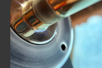
1766293996405.png

For example, getting rid of marks I circled above proved to be damn night impossible. The rest of the "scratches" are really just my greasy fingersmudges :).

Well, okay; with yoke polished, and the fixed cylinder polished, and bearing balls here, it's assembly time.

First, we drown the balls in silicone oil (I decided to use 100 cst here).

Then, caaarefully position them around the yoke. Don't sneeze! Don't breathe, in fact.

bearings.03.balls.stage1.jpg

Then, the fixed cylinder, and same thing there:

bearings.04.balls.stage2.jpg

And then, all that remains is the nut, locknut, and adjust for freedom and zero play.

Initially, I put the nuts on with no loctite - in case I'd need to take it apart again. Let's check that noise, shall we?


Well, this is quite underwhelming.... I expected the rumble to go away, but it didn't.... Could it be balls hitting each other (there's no ball separator inside)? What else.... I don't know...

On the other hand, the cylinder itself (the thing I'm spinning) is out of balance (due to that flat cut-out in it); that may be one of the reasons?

This is not a high-speed assembly; if the balls are hitting each other that would cause some of the rumble you hear; but in practice the arm is rotating oh so slowly this isn't a factor?..

And then again, holding the cylinder and gently blowing on the yoke caused it to move - gently, with no hesitation and no "jageddness".

Damn; I wish I could chat with one of them tonearm mechanics :).

Tell you what. I'll take it.

What was left was to take the nuts back off, and put them on with Loctite with final adjustments........

... at which point Loctite threw me off, because it cured under the lock nut faster than I expected
.. which made me think it was tight when I was checking the bearing
... which it wasn't, which meant that final tightening caused the main nut to be pushed down...
... which I should've stopped at, because I should've stopped and questioned myself: hey, why is the lock nut wanting to go for another full turn??..
... but I didn't and just tightened it...
.... which did push the main nut down, and promptly locked up the bearing...

I loosened it, and immediately found the sound to have changed - completely. Now I know! I was sure I dug the new "divots" by over-tightening it... which changed the sound... which means that I did something _good_ with all the polishing and machining... only to promptly screw it up.

Hoping for I don't know what, disassembled it.

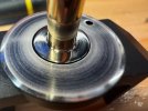
Yep. I made new divots....
bearings.05.screwup.jpg

.... but hey. Maybe that was Universe's way of showing me the ball contact area. Which was exactly the area where some machine marks were still present (most of what seems like "scratches" are again smudges of goop). Maybe re-doing this and trying to get as deep into that corner as humanly possible will improve this further...

Maybe this was Universe's way of convincing me that divots do make that rumbling noise, and polishing them out improves things by a mile (the noise went really, really downhill after my overtightening and loosening it).

And hence, the Bearings Blues.

We'll see.
 
Musings on the Hurst Motor

I know that one of the typical procedures for the motor is to pull the pulley with two spoons as levers, put a drop of oil on the shaft near the motor bushing, and have it spin for a long time. Then add some more oil. "Tighten it up" until there's no / very little play by gently hammering down the press on stopper. Etc.

If I may offer a bit of commentary...

But first; let's look at the motor. Sorry, this is not to scale :).

View attachment 3637573

When you pull the pulley, you will see the "press on stopper" and the top of the top "bushing". You won't see the "thrust washer" - it's smaller in OD that the stopper.

It's actually very clever. It's running in two bushings, with no bearing on the opposite end at all. Magnet is a "cup", hiding the long housing for the run bushings.

Over the years; the motor gets dirty; and whatever lubricant was in there gets stale. Best is to clean all that out. When it's run with a drop of oil placed into the top; that will eventually drain into the "cupped" magnet - especially if too much oil is put on. Then, it may throw off the cup's balance, collect more dirt, etc. Maybe I'm overthinking things...

I decided to take it apart - which is a reverse process of "tightening" up (by mildly hammering the stopper down).

Light taps with a 4oz hammer on the shaft, while holding the motor in my cupped hand (and with back cover taken off of course):

View attachment 3637577

... find the right (brass!) punch, and finish the job.
View attachment 3637578

You can see the shaft / magnet, press on stopper, and thrust washer here.

Now, this can be properly cleaned. This requires a smoking pipe (tobacco!!), good weather, good tobacco, good pipe cleaners, and a solvent (I used alcohol).

- Put the pipe cleaner into the bushings
- Drop alcohol on it (so that it becomes soaked inside)
- Pack a pipe, go outside, and smoke it (~30-45 minutes)
- Use pipe cleaners to clean the pipe
- Go back inside, pull the soaked and now black (!) pipe cleaner out of the bushing
- Repeat, until pipe cleaners coming out are completely pristine

See, you're supporting two hobbies at the same time now! - and also, you are making sure that - if these *were* oil-impregnated bushings - that you will pull all the old stuff out of them

Now, let it dry overnite.

Next comes the question of lube. Given that what's coming out as the process above is yellow and "oily", it might have been indeed oil impregnated bushings. It also might have been greased - do you see that space in between top and bottom bushings on my diagram? That could've had grease.

I do not know; and greasing would plug the pores on the bushing if it's supposed to be oil impregnated, so I decided to oil and monitor. If it needs more oil later, it's probably not oil impregnated :).

What I did was stick a pipe cleaner in there, soak it with oil, and leave that overnite.

Then, I cleaned it out again (mainly off of possible pipe cleaner fluff) - but without soaking! - and *then*, let it run in, *upside down* - with no collar and thrust washer - adding oil periodically (and letting it drip down and out and not fouling the magnet cup). In fact, it's running right now as I am typing this.

I heard somewhere that the legendary Mr. Marc Morin used to run these motors inside an oil bath "pod". That sounds very clever! It completely resolves the lubrication problem; and maybe dampens some vibrations that are happening when the motor runs (just run it in your hand while it's removed from the top plate and you'll know what I'm talking about).

--

Couple final words. The motor can still be bought from Hurst, direct; here: A, AB Direct Drive Permanent Magnet AC Synchronous Motors

Or, if you want a sub-project - and I am considering to do it later - there's a DC stepper variety, model 3007-001, AS, ABS Direct Drive Permanent Magnet DC Stepper Motors, which seems to fit perfect. I can imagine a little built in speed controller with 2 fine adjust pots, and a 3-position toggle - "45", "33", and "off". Right where the old rocker switch is; with pots maybe screwdriver-adjustable types hidden somewhere... This way you will never need to flip the belt to the big side of the pulley too. I wonder if this is what was done on TTs where there was an external speed control box.... I have seen it somewhere...
I am a original owner of this same turntable and I never had a problem with the motor I just upgraded the pulley, Tonearm and Springs
 
Mine had the original pulley that was bent on edges, as if someone tried to grab it by the edges and pull up....

By the way! I said something in that motor musings post that is inaccurate. I said that Mr. Marc made a mod for it to run the motor in an oil bath. I heard that somewhere in passing.

Since then, after a ton more research, I realized I was wrong. The "pod" is a clamp of sorts. I actually think I am on a lead to un-tangle the puzzle of the "Morin Motor Pod" and precisely what it does and why. More to come on the subject in later posts - I am still testing things out over here!

There's no specific problem I was solving. It's just an old turntable - which means motor's dirty, bearings are tired, and .. well, see all the suspension stuff Marc Morin has developed sprinkled all over AK that can be done to any condition AR to make it better-er.

See, I am a glutton for punishment - and I almost (masochistically) enjoy tinkering with these things more than using them.

You know how they say that music lovers like their music and audiophiles like listening to their equipment? I think we need a third category - "audio mechanic". Guys (and gals) that like messing with their stuff. I would be of a "backyard redneck audio mechanic" variety then ;)

In other - immortal I might add - words, we do what we must, because we can [and the cake is a lie guys!]! Hehe.
 
Last edited:
Intermission: Polising

Well then folks, after yesterday's fiasco, my today was pretty much set in stone. Redemption!

But first, I just realized... I never really described the process. Because such a simple thing - polishing! - caused me so much grief, and noodling, and because the goal of this thread is to "leave more breadcrumbs for someone like myself to find and see what happened to another guy trying to do the same thing", let me describe it.

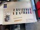
I use MicroMesh sanding sticks and foams. Now, sometimes it's helpful to have just the abrasive, without the foam "cushion". Flooding it with WD40 will release the glue and release the cloth backing from the foam of the MicroMesh.
Here's the picture of the arrangement. You can see the original MicroMesh pads in the baggie as well.

1766387670215.jpeg


The brush and the popsicle stick (or a tongue depressor, depending on whom you like better - doctors or ice cream) are gonna be used to hold the paper. I'll show this in a bit.

Here is what you're ultimately trying to do. Think of sandpaper as a rake. The smaller the grit (the higher number); the smaller the teeth. You want to have your first (coarsest, lowest number) grit to be close to the "feature" (scratch, or divot in my case) you're trying to remove - because imagine what will happen if you're trying to fill a man sized hole with a kid's rake with 1 inch teeth. That ain't gonna work. You first need a dozer; then a plow, then a rake, and then a leafrake.

Same idea here. We find the finest grit to remove the feature, and go up from there. Each next grit will take out the scratches of the previous one, and make it's own (smaller) scratches. We stop where we want to - here, I stopped at 12000 (because MicroMesh doesn't go higher ;) ).

And here's the process.

1. We do this wet. I use WD40 as lubricant

2. As you sand, lubricant and chips (and small chunks of grit that may have broke off the cloth backing) will form a "slurry". Slurry is your friend. You can tell that you're doing something, and you can see where a "band" of the slurry is floating on the surface.

3. Flushing between grits is critical - you want to make sure all the previous slurry is gone; otherwise, you may pick up a larger grit when sanding with smaller (less coarse) one.

4. I hope this should go without saying, but you can't skip grits! Otherwise, you will "round over" the tops of the scratches made by the previous grit; but not remove them completely.

5. You have to spin your workpiece (or your sandpaper); the idea is that the revolutions are faster than the motion of the paper. This will ensure evenness, sanding by hand will very easily throw off the geometry. I have - thanks God - a lathe, and not having that I probably might've attempted to use a hand drill to hold my workpieces and spin them...

Before you begin, you need good vision.. and good light. Let's find those "dork glasses" as I call them :)

1766386536728.jpeg


And we need to be able to examine our handiwork. Slowly watching in a reflected light thru the above works. iPhone cameras in macro mode are great! USB microscopes... pick your poison.

Let's make some slurry?

1766386591529.jpeg

I am holding a chunk of micromesh here around my round "mandrel" brush, moving it slowly back and fro. Lathe's at 500ish RPM. Not too fast, not too slow.

It takes about 15-30 seconds for one grit "pass". When done, this is what you should see:

1766386642733.jpeg

Notice a good smear of the slurry / materal on the paper. If you got a bald spot, you're pressing too hard. If you got just one spot with virgin paper all around, you haven't moved it around enough. That is one of the bits that takes practice to figure out (took me quite some practice, at least).

Now, remember, I said that your first (coarsest) grit should be enough to take off the "feature" you're trying to polish out? In my example, it was the "divots" from the fiasco yesterday.

So how do I know where to start? Well. Gutfeel and experiment. :)

Let's try the coarsest micromesh I have, 1500 I believe?

1766386871677.jpeg

Nope!

Divots still there.

Let's try to go lower, let's say.. 800?

1766386919491.jpeg

Do you see one lonely divot there? :) Nope, still too high.

400 looks better, but as we progress back up the grit (800 - 1000 - 1500), we see some weird "ridge" developing.

1766387017080.png

Hmmmmm...

My theory was that this was technique - I would do the face (white metal part) first, and then the brass tube with a "band" of paper looped around it. I am suspecting that the edge of that "band" digging into the face. Let's try flipping the sequence: we do the band first, and then the face. Back to 400, and redo the 800, 1000, 1500...

1766387185466.jpeg


... and so on, and so on, and so on.

You are trying to get your next round to look like all the scratches from the previous round are removed.

When done, stop, clean, dry, congratulate yourself, and move on to whatever else you were gonna do!
 
The Linn Basik LVX Musings - part 3: The Bearing Rock-n-Roll.

So all that description of polishing.. But how did I do?

Well.

I was chasing my own tail. Sanding into the corner is damn nigh impossible. I tried a bunch of different "mandrels" to wrap the paper around. Popsicle stick. Screwdriver (thinking it'll be a more rigid surface). A dental type brass pick.

I would always get weird scratches that still remained, and show up 2-3 grits down the road. Like this:

. 1766388100855.jpeg

I ended up settling on the following, after adding sanding sticks (also MicroMesh) to the lineup.

Face with sanding sticks:

1766388301710.jpeg

And corner with popsicle stick:

1766388317587.jpeg

.. and still, getting into that corner proved damn nigh impossible... But, the divots are gone..

1766388383427.jpeg

1766388496921.png

Looks like crap? You betch-a!

First picture shows marks still present near the corner. Yep, I was not able to get them out of there :( And the second picture shows marks on the.. brass tube? How's that possible?

That threw me for a loop too; until I realized that I was looking at *reflections* (my dork glasses from the above post helped here). All the white stuff is micro-droplets of solvent and remaining WD-40 by the way...

Do you see how I undercut the "base" of the brass tube by all my trying to get into the corner?

Not good.

What did we learn? Sanding into a corner - at least, with my technique - is damn nigh impossible. Thinking about this more, I think that a much better way would've been to machine another one of those race washers - the "face" I was trying to polish. Machine the old one out, pre-polish a new one (easy!) and put it in.

Live and learn. I am not going to do that, because - ultimately - I also - thinking in between all the sanding - came to realize that if we're doing that, a much better fix would be to just put in the ball bearings in there, instead of this loose ball arrangement. This is - in fact - what I understand the difference between Basik LVX, Basic Plus, and a later Akito variations of this tonearm are. That is a proper fix.

I grew fond of this tonearm. I like how mechanically simple it is. I very well might - in the future - get one more, and do a proper job on it. I am thinking nice bearings for the pivot, and needle / sapphire for the up/down pivot. But that's for later, right now I am trying to just improve a tonearm I had for this turntable - so that I can actually proceed to using it to do the chassis mass loading, and such.

Sounds like blues, again?? Well :) Blues and Rock-n-Roll are the same thing, really, aren't they? The other is just.. happier :).

So, did I improve it?
You betcha!

Remember where we started?

1766389031814.png

... and so, I put it back together.

1766389073294.jpeg

I left just a tiniest touch of slop in the bearing. You see, my original thinking was that any slop was bad - but I am used to motor bearings. Machine tools. Wheels :). Here, this is not a fast rotating assembly, and it moves just a handful of degrees in one direction, *continuously*. Yes, initial "move forward" will tilt this - just a touch - and then the bearings will get loaded, and continue the smooth motion forward. From the perspective of the stylus though, the arm should be solid - even with this tiny bit of slop.

Alternatively, if I took all the slop out, with such a tiny ball size, I will be scared about any tiniest speck of dust getting under a bearing ball.

I decided not to use Locktite on the nuts, to prevent the same fiasco. Instead, just the jam nut snugging, and some external "torque seal" from my local grocery chain's torque sealant department. Oh, you didn't know each grocery store has one? It's usually huge, and offers torque sealants in all kinds of colors. Even with glitter!

1766389362229.jpeg


So how did I do?

Here's a "blow" test and a spin test:


I think that looks good!

Now, a thing that threw me for a loop, for a long time.

As I was playing with the now reassembled bearing, I noticed that it would sometimes bounce "back" as it comes to a stop.

Here, check this out:


Sometimes, it would stop, then rotate back just a touch. Sometimes it would not. I started having all kinds of bad thoughts about divots again - basically, thinking I somehow still had those divots, and a ball would roll into it, not make it "out", and roll back down the hill.

Maybe. But then again, the "spinning" was perfect - it was just when it came to a stop when this "bounce back" will manifest.

I am still at a loss here guys. I know I did not overtighten it this time, because I would tighten it literally by singles of degrees, and making sure the slop was still there. It hadn't ever gone away. The bearing sounds good, too.

My current theory is that it may have to do with the slop I left in. As it spins, forces are stable, with spinning part tilted in a particular orientation to take the slop out, but as the rotation stops, it settles "down", causing the counter-rotation.

Regardless, I am leaving this alone. This is way better than what I had :). And enough of this "machine shop for audio enthusiast" stuff already. I promise, next we'll have some real tonearm repair stuff! :)
 
The Linn Basik LVX Musings - part 4: Headshell!
After all that fun with bearings, machining, screwing up, sanding, re-machining, re-doing, and brooding, let's do something nice and easy: a headshell?

[side note: this and the next couple posts are not in "timeline order" of how I did things; I shuffled them around for narrative purposes :). In reality, I was doing all these things - headshell, wiring, and assembly - at the same time - as a story; it works better in stages. Otherwise, I'd be like that Donnerjack book (if you read it, you know what I'm talking about, and if you didn't... it's not a bad one - if you like cyber-punky weird mystical sci fi :)].

Headshell connector on my Linn Basik - the one I spent so much time doing bearings on - is pretty tired. It's sockets - the ones that connect to receptacle's pins in the wand - are loose, and, given what this connector is, it's impossible to "tighten" them. Besides, I'm sure there's corrosion and residue and such - so why not change it?

Now, Linn was clever. See, wand side it's pins (they don't wear out!) and headshell side, it's sockets. Headshell is considered disposable here; and you can always get a new one for a few bucks! - ... except that, well, they no longer make them :).

A bit of research showed that Linn Basik seems to be using an "ADC" connector. I couldn't find a source for the actual connector bit; but I did find a source for headshells! - Turntable Needles sells LMH-1 Lightweight Headshell for ADC straight arms. I don't care for the light weight - but I wanted the connector!

Bought a couple - they're cheap enough. Of course the connector is glued in, and wouldn't bulge!

Time for some liberal application of vandalism?


1766978662282.png

That was nibbling away with side cutters.

Now; a bit of knifing:

1766978688863.jpeg

and the connector is free!

Now, we can't vandalize the actual Linn headshell in the same manner. Lucky for me, it's made out of aluminum - so here was the plan.

I made sure that I can melt the connector (with my heat torch I used so much to loosen loctite on various fasteners, and that I continue using for heatshrink).

I was going to heat the headshell in the area where the connector was - as evenly as possible - hoping that the glue would release. If it woudln't, I was ready to go as hot as necessary to actually melt the outer surface of the connector, so that it will slide out.

... which is what ended up happening:

1766978859923.jpeg


I checked the connector that I "vandalized" out of the LMH-1 headshell for fit. It was perfect, and tight - I decided not to use any kind of glue at all.

Now, one final gripe I have about these headshells. I don't like the folded-sheet-metal in folded-sheet-metal connections for cartridge lead wires.

These ones:

1766978985259.jpeg

They just feel.. jenky and crappy and meh.

Now, I *do* love me some machined pins! Searching a bit, found Zavfino's headshell leads - and they are excellent! - except that.. my connector on the headshell side isn't the right type for them....

Let's solve two problems at once?

1766979129394.jpeg

I removed sockets from one side of each of the Zavfino's wires, and those wires fit perfectly *into* the sockets where that "knife" would fit into with standard leads. A bit of solder - and we have a much better than a mechanical connection! Win!

And, finally, we have a pretty good looking headshell, with new connections and beautiful cartridge lead wires, all done!

1766979219483.jpeg

We will need it, very very soon.
 
Last edited:
The Linn Basik LVX Musings - part 5: No More Denial, We're Rewiring It!

Remember how I was non committal about the whole Linn rewiring business? "Still not committed to rewiring", I would say?

Well, enough of this nonsense. We got the darn thing in parts right here, what's extra 10 solder joints?

To rewire, I got a couple of options to sample: because I liked Zavfino's headshell pins and leads so much, I ordered their Litz wire; and - having read a bunch of good thinks about "KAB Superflex" silicone covered tonearm wire, ordered a kit from him.

KAB wire is superior guys. It's insanely flexible. Mr. Kevin at KAB says "like a wet noodle"; and he's not wrong!

The only thing that Zavfino has going for it is that it doesn't require prep for working: you just tin-n-go. KAB needs to be stripped.

With Linn, I was gonna start at the headshell side - or rather, the wand's headshell connector side, because that's required for proper order of assembly. We will talk about the assembly next!

To heat sink and have a holder, I stuck the connector into another LMH headshell I got from turntable needles (see the above post on headsheel). That will also prevent wire color mishaps; I could just trace the headshell's wire colors into the pin I was soldering.

Not having anything better at hand, I decided to use an old trick with scoring the insulation with a razor blade, and pulling it off to strip. This wire is tiny!

Here's the stripped wire, being tinned

1766980649321.jpeg

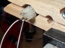
... and you can see the connector on the left in the main opening of the clothespin :).

First connection made.

1766980683876.jpeg

Looks.. pretty okay?

Connected the other three, did a cursory resistance check [seemed in the ballpark between one another], and did a shot for the post:

1766981161522.jpeg

Wait.... WHAT?! :yikes:

Oh no... Apparently, this will take a TON more than just winging it. iPhone's macro mode saves my butt. I would not have seen any of this w/o this picture, guys. Even under my 2x headband magnifier, it all looked presentable.

So let's analyze this.

First, no more acid brushes when cleaning flux (I am sure that birdcage on the green wire, and the sharp bend on the red wire, happened because of that).

Second, I am clearly nicking the strands with my stripping method.

And third; the pins themselves are juuuust junky and need some TLC.

Let's start with stripping. Or rather, let me just say - that threw me for such a loop that I ended up starting a whole separate thread here on the subject. Here, read it if you are so inclined :)

Pins are an easy fix. A bit of the wire brush; a bit of the sandpaper where the wire brush can't get to, a bit of re-tinning makes them presentable enough.

1766981494489.jpeg


... and finally, let's try again - before we run out of wire trying to convince ourselves "one more time" that we cracked the stripping problem.

1766981556508.jpeg

There, much much better! This is actually pretty presentable.

Now; for the record - here's the actual detailed soldering process.

1. Strip the wire ( :) )

2. Smear some flux over it, and burn the Litz lacquer + tin it by dragging it thru a bead of liquid solder on the iron's tip (I use MG 8341 as an experiment currently, my previous favorites were Kester 186 and AmTech RMA-TF. Latter two are milspec - and I love milspec everything; long story - but milspec stuff is harder to clean than MG 8341; so I am experimenting).

3. Make sure it's thoroughly tinned!

4. Clean everything off - there'll be flux residue, and residue left over from Litz lacquer burning off - alcohol works good here, and it will take some effort. You should be left with silver colored tinned wire.

5. Assuming the pin is tinned - if not, tin the pin first! - smear it handily with flux

6. Position your solder right next to the work area, you will not be able to hold it!

7. Wire in one hand, touch it to the fluxed pin. It'll stick a bit. Hold it. With another hand, make sure your iron's tip is squeaky clean, pick up a tiny bead of solder, and heat up the pin - flux will flow, and wire will follow.

8. Repeat for 3 other pins.

9. Clean off all the flux.

Couple more points.

Eutectic solder is critical here (63/37, I use a version with 4% silver because I can! :) ), because you're holding the wire and it's not fixed - solder needs to "freeze" instantly, or you'll have a bad joint.

Careful when cleaning the flux off the connector - don't mess up the wires! I gently brushed off with a watercolor brush (not my usual stiff acid brush), followed by a liberal spray of CRC QD Contact Cleaner (this stuff is AWESOME to flush flux residue, especially off of PCBs). Let dry after contact cleaner (it'll cool the works off enough for them to pick up some dew from the air).

Inspect, inspect, inspect! I took macro pictures the moment I would suspect something could have gone bad. Even sometimes of the "hole" in the "insulation noodle" - to make sure no stray strands were left there.

1766982700105.png

Do you see one? :)

... so after all that fun and excitement, I took resistance measurements for each wire. Since holding them with a probe is damn nigh impossible, I tinned their other ends, and would solder them to a cut off probe wire - while using a headshell pin on the other end.

I would write them down, and keep re-checking them after doing any operation having to do with the wires when assembling (next post!). This, I thought, would provide some assurance that I didn't mess anything up in that step.

... well, and finally: heatshrink will cover all manner of sin? :) Not much sin to cover though I think.

1766982885921.png

Why are they not to the bottom? Clever question! They heat up better like that, and I have a little area to put my test probe in should I need to.
 

Attachments

  • 1766982857371.png
    1766982857371.png
    830.2 KB · Views: 2
The Linn Basik LVX Musings - part 6: Let's Stuff It! (And Mostly Assemble It, Too!)

So I am dangerously close to getting back the tonearm - which will finally allow me to start properly balancing the subchassis (need the tonearm to do that :)).

For the attentive ones, you will see differences in pictures. These pictures are from two different attempts. Some pictures from attempt #1 illustrate things better than the pictures I had for attempt #2. So that's why.

Now.

I had the main bearing already built (a few posts back, right?), so wand and pivot come next.

I read a bunch of threads and other things about tonearm deadening. Heatshrink on the outside. Latex tube on the inside (KAB for Technics). Cotton. Balsa (I have convenient balsa pipe filters - smoking pipe that is - that seem to be made just for that job - with "channels" milled for airflow, no, pardon, wires! - to boot). Earplugs!

Marc Morin seems to have been strategically positioning earplugs inside heatshrink lining to deaden the tube at just the right spots to "tune" it. I found references to that here and here, among other places.

I can't do the math on where to place the plugs - I don't know how. Maybe this will bite me; but I decided to stuff as much of the wand as possible - we shall see...

After a bunch of experimenting with stuffing earplugs into the wand, and trying different heatshrink linings, here's what I decided to do.

Here's everything that will go into the tube, in that relative positioning and arrangement:

1766984891600.jpeg

Immediately behind the connector (headshell on the right here), we will have a sleeve of "empty" heatshrink - to give wires and pins some room. Then, all the way to the tail, we will have a section of heatshrink lining the tube, with earplugs stuffed inside (you see only one earplug on the picture, but in the final plan there'll be earplugs all the way to the end of the tube).

The heatshrink is cut along the length to allow "squishing" it for easy insertion. Expanding plugs will press it against the wand's ID walls.

Let's attempt to execute.

So, step one is pretty basic - stuff the single chunk of HST into the front of the wand, positioning it so that it starts just where the headshell connector's white body stops. That took a couple of retries, but no problem.

Now, we measure how deep the back side of the chunk is, and cut our sliced heatshrink -- to be stuffed with earplugs - to final length.

That leaves us the wires, right? We need to fish the wires thru somehow. Here's the arrangement:

1766985191763.jpeg

Notice that our cut length of HST is now fully stuffed with the earplugs. Each cylindrical earplug is cut in half, with flat part facing down. There's a thinner tube now inside the heatshrink sleeve - that's a coffee stirrer stick.

Here's the idea. When squishing, we will close the cut heatshrink around the earplugs, allowing for easy insertion. The plugs themselves will form around the coffee stirrer (which is hollow). We will insert the "assembly" like this - with the front of the stirrer being flush with the front of the heatshrink (and tail of the stirrer sticking out from inside the wand). We will then use the stirrer to run the wires thru it, and, when done, pull the stirrer out - with plugs now closing up a bit where the stirrer was, but not so much as to squish the wires a lot. The whole "half plug" idea came from @Hose53 - "fold it like a tortilla", I read somewhere. Yep! My experiments confirmed this ingenious move.

So, shall we proceed to insertion?

1766985422000.jpeg

Clocking is important - in my case, I wanted wires on top (because of the wand's tail geometry; it has a ground tab on the bottom). I checked the clocking and absence of twist by shining the light thru the coffee stirrer, and making sure it's still straight.

Once fully inserted, we can fish the headshell's connector wires thru. I just stuck a length of bare 24ga thru it, soldered wires to it, and pulled them thru. Did you guys know that coffee stirrers have an internal rib, splitting the ID into two "chambers"? :) This helped actually, by keeping two pairs of wires separated I ensured less chances of twist.

1766985608587.jpeg

Then, we install the headshell connector. But first, my headshell collar had a couple screws that I removed, let's put them back.

1766985690003.jpeg
Ugh. I don't like that at all. It protrudes into the wand waaay too deep. Shortening it isn't that hard though, a bit of sanding and a bit of smoothing the end and we're in business.

.. so the headshell connector is now in. I gently pulled it in with the wires, stopping at any resistance and helping it if necessary. Final ~1/16th of an inch I didn't pull the wires at all - instead, moved the connector all the way to the stop. This created some slack in the wires just behind the connector. This will give wires some length to move if the earplugs, expanding after I pull out the stirrer, will want to move them.

... and finally, to pull out the stirrer. That is tricky! If you pinch it too hard, you risk grabbing the wires along with it. When you pull on it, the whole lining with earplugs might start moving instead of just the stirrer. To solve that last bit, I ended up holding the lining inside with a BBQ skewer while pulling the stirrer... I quickly realized it's too slippery and I was afraid to pinch the wires... in a flash, I thought "hell, lemme put on a length of heatshrink with glue lining over it, that's longer than the wires - this way, I can grab it by the empty end all I want and not damage anything, and, hopefully, glue will hold onto the stirrer".

1766986183032.jpeg

Stupid stupid stupid! I flicked my torch in a wrong way, and immediately melted the stirrer. Do you see it? In another stupid move, I decided to try pulling it anyway - hoping that the stirrer didn't collapse inside enough to grab onto the wires. As you can probably tell by the picture (of the pulled out stirrer and wires still there), this time I got super lucky.

To be sure, I triple checked the resistances (still good!) and cut off that melted chunk and looked inside.

1766986300922.png

Phew... I still see a hole.

... the rest of this was fairly uneventful. I used the same 24ga bare wire trick to pull the wires thru the tail block, and screwed everything together.

1766986377479.jpeg

Checking resistances from headshell clamp to ground wire, discovered that my replacing the screws around the ground tab connection caused that resistance to shoot to about 100 ohms! Mine were regular M2s, Linn originally used self-tapping types, that have triangular shape to them - being just a bit thicker, they "cut" into the ground tab inside the wand to make that connection. So, leaving old Linn screws there.

Then, one final cleanup of the pivot bearings, a drop of 100 cst silicone into each one, and I installed the wand onto the yoke. Used loctite on pivot pins, will not use counternuts (well, I'll put them back on for decorative purposes) - I don't like locknuts throwing adjustments off, and blue loctite is more than enough to hold the pins.

Set it up for just a tiny bit of up/down and side/side wobble, and to be as evenly spaced in the yoke as I can (I think I got it within a thou...).

Tested the "float"; both up and down and left right. Very nice! These wires are not perceivable, none whatsoever. Slightest air motion makes the tonearm deflect up and down, and just touching the antiskate causes it to move "off the peg" (my tick marks starts at 0.5 antiskate, the "barely off the peg" position is probably around 0.1 spot on the dial) causes the arm to rotate in the antiskate (outwardly) direction.

Well, it seems to be coming together, and we've got ourselves something resembling an original tonearm! What's left is putting it into the base, soldering the 5-pin onto the base end, and we can - finally - start mass balancing the chassis :).

1766986799221.png
 
Last edited:
This project is not dead.

Nope!

It's just... many, many other projects managed to sneak their sneaky sneakiness in front of this one. Once again, broken cars, broken... other mechanisms, 12U baseball, and....

Well, we all know how life goes.

Last we left, the tonearm was almost together. It is, finally, 100% together - the rest of it isn't that interesting in terms of pictures - just more soldering (5-pin DIN connector on the bottom) and whatnot.

Oh, a public service announcement - guys, if you are gonna spend money on good strippers (which range from 50 to 250 for "reasonable"), get yourselves a thermal Strip-All - used. Clean it up, replace its power cord with flexible silicone test leads, and get new blades (cheap); used Strip-Alls can be had on eBay for around $100. It's a life changer. Stripping those tiny tonearm wires (and pretty much anything else) is now a non-event. The only disadvantage is that it's a bench stripper; using it on the go is not good. Get one with an adjustable power supply - so that you can control the temp.

At any rate, with the tonearm now complete, we get to the most interesting part - suspension tuning a-la-MarcMorin.

I'll split this into a few separate posts. The first one is:

Suspension Tuning Musings pt. 1 - The Setup.

My springs are from Vinyl Nirvana; they very closely match - if not are - the Linn springs Marc used. .065 wire, ~43mm free height, 11ish turns.
Marc positioned weights in strategic spots to compress them to 30-32mm - evenly - to achieve what he called 'jounce': a minor deflection down at the T-Bar CG should produce ~3.5Hz up-down oscillations and nothing else (no side-to-side jiggle).

There are a few versions of how the weights were done - stick-on wheel weights, screw-on lead pucks. It seems that towards the end, he started using a "collector" plate - basically, a plastic piece that goes as low as possible under the T-Bar, and moves the weights as low as possible. This makes sense - it makes the system more stable (think: a pendulum suspended from the top, a-la a clock).

This collector is also quite heavy, contributing to the weighting down. Pretty good!

So my plan for the weights' setup is to repeat one of these later setups. It can be seen here, for example: https://audiokarma.org/forums/threads/official-ar-turntable-owners-thread.595003/post-16868774 The black plastic triangle is that "collector".

Then, spring perches. They're talked about a lot here. Here's one thread: https://audiokarma.org/forums/threa...”-replacements-with-pics.378703/#post-4776381

VN springs come with rubber "perches" - the T-shaped fittings that will go onto the top-plate studs. My understanding is that Marc tried to make perches concentric and immobile - so that the spring's bottom doesn't move side to side, throwing the tuning off. The perches are _nuts_ - threaded onto the studs . This sets them solid, and provides a square to the stud, rigid "shelf" for the spring to sit on.

Finally, the jig. It's visible here: https://audiokarma.org/forums/threads/need-a-ar-xa-measurement-please.440285/post-5710018 - basically, all it is is a repeat of the T-bar shape. I suspect what it really does is position the perches at precise spots where they will be on the turntable - so that everything matches up during tuning.

Let's talk about oddball parts first.

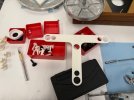
The perches I made out of Delrin. The spacer bushings that will position the "collector" down - 3/4" away from the subchassis - I made out of some 1/2" PVC.

1790379136798.jpeg

1790379149991.jpeg

The collector I prototyped - a lot - as a 3D print first, and then used it as a template to cut the real thing out of 1/2" Delrin sheet.

1790379202965.jpeg


... and the jig:

1790379237502.jpeg

The larger holes on the tips are where the perches fit snugly. The smaller holes are for height gauges - to measure spring compression easily. I printed three each of 33, 32, 31, and 30mm gauges - with 1/8" added for the spring perch "base" thickness. They go in holes instead of on the top of the jig, so they touch the reference surface (the same one on which the perches are set), because the jig is not perfectly flat - it doesn't have to be; it just sets up the hole distance.

1790379379251.jpeg


I thought quite a bit about the setup. I don't know the weight to go with, so I will need to first set everything up, figure out the weights and positioning, and then transfer those weights to the bottom of the subchassis on the collector, into a position closely matching the one used during tuning.

Let me show you the setup I ended up arriving at.

1790378626008.jpeg

Bottom to top: granite plate on top of 3 screw jacks (for leveling the jig). 3 1-2-3 blocks on top of the granite plate in the right position, and all that is leveled.

Perches go on top of the 1-2-3 blocks (reference level surface). My height gauges will sit on top of them too. Spacing between perches is set by the white printed T-bar jig.

The springs sit on top of the perches.

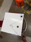
The collector (the white triangular piece on the top) is set up so that the center hole is concentric with the spindle - and, at the same time, its front edge is flush with the T-bar's front edge. This way, I have a repeatable setup:

- when tuning, the collector is initially on top of the platter, positioned by the spindle and with its "tip" pointing at the centerline of the T-Bar (you can see a little white "arrow" on the tonearm armboard - that's the CL "pointer" - the platter's CL is lined up with that, and the collector is lined up with the platter's CL).

- then, when drilling for attachment, the front edge of the collector is flush with the T-bar's front ("top" of the tee), and left/right is locked to the the CL of the "stem" of the tee.

The collector also establishes "no-go" zones so that the weights won't interfere. It's kinda obvious if you look at the whole thing inside the chassis (the red box is a "simulated weight" :) ):

1790379471213.jpeg


Well, and that's that: then, I will slide my height gauges under, and start putting the weights at the tips of the triangular collector, to get to 30-32mm compression.

And that, boys and girls, will be in the next post :).
 
Suspension Tuning Musings Pt. 2 - Initial Weights.

So, with all the bits at the ready, it was the time to try this out.

First, set up the granite plate and level it. Three 1-2-3 blocks' tops are the reference surface, so after rough leveling the plate, the final leveling is done across the 3 blocks.

1790384644902.jpeg

If you see the level is not "dead nuts" - it ain't. This is a super sensitive level; me *breathing* on this setup makes it move a bit. It's close enough, trust me :).

Then, the perches in the T-jig and the springs go on top:

1790384724900.jpeg

And then, the subchassis, platter, tonearm, the whole nine yards.

I used a cork mat that is ~50 grams heavier than the final mat I will be using, no record, a throwaway cart... No cable plugged in - but the connector is there.

1790384804111.jpeg

Notice how off (compressed more than the other 2) the tonearm side spring is?

... line everything up.

1790384852114.jpeg

well, and just play with weights.

1790384868376.jpeg

My final weights are gonna be made out of 2x1 bar stock, and the boxes are 2 inches wide - to represent the rough footprint. I fill them with various wheel weights, trying to get exactly on height at each of 3 springs.

Those height gauges turned out to be extremely useful:

1790384960330.jpeg

I could actually slightly push down on a corner I was tuning, and "feel" where it hits - which gave a great feedback of how far. Mind you, this is a rough tuneup - actual weights will walk a bit with hardware added (I tried to simulate it with an added 1oz puck to each box), and general inaccuracies - final tuning I will probably try to be more precise than this.

Shining a light and watching the shadow play on the spindle well's outside wall let me judge if the jounce is straight up and down or there's some side wobble to it.

1790385076810.jpeg

And so, how did we do?

The first thing I noticed is that my tonearm spring was already at 32mm, with no extra weight. Pondering this a bit: most pictures you see have three weights (one on the tonearm side), and I at 32! Why?

Most pictures here are of the AR-XAs - which have a very different tonearm than mine. I am fixing "The Turntable".

Plus, I am using a Linn tonearm (which is heavier than stock AR). That explains why I need almost no weight on the tonearm side; and re-watching relevant segments of BlueGlow's MarcMorinised "The AR" video, he has the same thing: no weight tonearm side. Great!


I targeted 31mm compressed height (because I was right at 32 with nothing on the tonearm side); I can always go more compression, but if I overdo the weights, I can't reduce it w/o removing everything and trimming.

We got to 583 grams in one box and 589 grams in the other. That's darn close! (within a quarter oz). Order of magnitude checks out too: ~1 lb 4.5 oz per side.

Tonearm side got just 3/4oz.

I will probably make 2 weights of the same mass, and trim with wheel weights (collector plate makes for a real nice surface to attach them - on top of it). Probably 580g for a round number (and throw it off immediately by drilling the mounting holes, yes ;) ).

Well, and what about the jounce?


And I tried to get you the wobble video - without any mass loading - too. Tried to do the same deflection. The wobble is there, it's very hard to shoot reliably for some reason - this is the best I could muster. You can see it if you watch the shadow on the spindle well OD, or the spring nearest the camera.


Next, making the actual weights, re-check, and mounting.
 
Last edited:
Interlude: AI Slop

If you don't care about AI stuff, don't read this post. :) It also is a bit computer nerdy, so please excuse me.

For narrative purposes, though, to make sure the next post makes sense, I figured I would post this one here too. It may have something useful to someone. :)

I have read - and researched a bunch of - Marc's threads on all kinds of various topics. I was afraid that I am missing stuff, am failing at finding stuff, or - generally - wanted to be able to easily traverse the full "Marc Knowledge Database", efficiently.

Gladly, I do have access to some AI stuff, and I decided to try this: make a full archive of Marc's knowledge that I can later query with AI. "Hey, how did Marc's thinking evolve on subject X", etc. I did that in spring, on and off - took me about a week.

Here's how it was built.

The idea was, I would have my AI bot do the same exact thing I would - just faster. Read the threads and collect all the information into a series of text files.

So my AI chatbot was driving a web browser - the AI bot was clicking the buttons and typing things in, literally. We started with full search by author - marcmorin.

Then, read each post, and read enough posts "back" and "forward" to reconstruct full context - because some posts can be "yes", "no", or similar, and I didn't want to lose anything. So, for example, if we found a post by Marc saying "yes, I do", we would read "back" to find the question he was answering (could be pages back), and save the whole thing - both the question and the answer ("Marc does do STUFF" in the example above).

Well, guys. Here's a fun fact: Marc's Knowledge File is about 8 megabytes. This day and age, this is nothing, right? Well, not till you consider that this is text. War and Peace by Leo Tolstoy - a HUGE novel - is 3.2 megs. So about 2.5 times that.

After having the text and a simple index, I could then ask questions like the above. I tested it on a few I knew answers to - evolution of mass loading (wheel weights to lead pucks to "collector plates" lower on the subchassis), tonearm fixes, etc - and it all seemed to connect.

Which led me to - finally - try to find everything on the subject I was failing at figuring out myself with my reading and searches. And that's the topic of the next post.
 
The Motor Pod Musings: frustrations, and more AI slop

Motor Pod was the last bit that I wanted to do to the table - before final assembly. Pictures of it are scattered in various threads, and there's even a thread discussing some testing of it done here: https://audiokarma.org/forums/threads/marc-morins-new-ar-tweak-w-sound-samples.487079

From what I understand, the idea was to basically clamp the motor to the top plate harder. Or maybe not... Maybe it was the clamp and some vibration soak-up magic gizmo... I was never quite sure. But on the pictures, I invariably see a wooden or a Delrin plate, with a hole in the middle and a rubber-type puck sticking thru it.

There were mentions of "quiet" and stethoscopes. So that was the first thing I tried - just listen to the motor running with a stethoscope on one of the studs and / or the top plate. Idea was, I would try my "pod" and see if anything changed.

Well, I very quickly found out that a stethoscope I had was drilling holes thru my ear canals with its tips - that's how hard I had to press it in (yes, it's a crappy one).

So, I built a better stethoscope. I will admit to this setup also being AI slop - I had an idea of putting a mike on the top plate and amplifying it somehow, but precisely what kind of mike I used an AI to figure out.

Here's the setup.

1791007130535.jpeg


Mic is a piezo disk, Mouser part # 490-CEB-35D26. It goes into my QA403. The more I play with the QA403, the more I love it - it's super versatile. Had it for a couple years now. There are ASIO drivers for it - GitHub - dechamps/ASIO401: An unofficial ASIO driver for the QuantAsylum QA403, QA402 and QA401 audio analyzers. - which let you feed input (and return!) thru a computer. I could've used an audio interface, but I don't have one - and QA403 is "instrument grade" anyway :) - much better. And can be an audio interface.

So the chain looked like this:

Piezo -> QA403 in -> PC -> QA403 out -> headphone amp -> headphones.

Mistake #1 - didn't ground the top plate (onto which the piezo was glued). I was picking up all kinds of 60Hz power line hum and could barely hear anything. I suck at this, so had to involve my AI slop generator :( - which initially suggested JFET buffers, until I told it that my piezo is wired _balanced_ - and the bot told me to ground the top plate. It made sense when I did it, but idiot me would've taken a crapton of time getting there.

First off - this "stethoscope" is insane, by the way. It could "feel" - and I could hear - me typing at my keyboard, positioned on a separate table ~4ft away from the setup.

Second. I could now not rely on my ears, but rather record sample tracks and analyze them, seeing what my changes actually do. I used REAPER for recording (eval license, and it can do ASIO in / out) and REW for spectrum analysis.

And this is pretty much the only useful stuff I achieved here...

I suck at this - I am not a vibration analyst, mechanical engineer, suspension systems' designer, or any kind of EE. I understand FFTs and what I'm looking at, but I don't know what to look for - you know... a guy who doesn't work on cars can't pick up a faint whine of a bearing a guy who saw a bunch of bearings can...

But hey. AI slop, right? Besides, I have my ears - if things get quieter, they - well - are quieter. Right?

So, the pod. I made a similar Delrin plate, bolted it on, and... nothing I could audibly detect. REW showed the same thing.

... and then I went on a massive goose chase, talking to my AI dummy, and trying different things, making it read engineering manuals and design the thing based on first principles, or use my Marc Morin's Knowledge File to try to reverse engineer what he did.

... and we failed.

Motor pod on / off does not do anything. I tried with the back cap off and pressing right on the motor coil, back cap on, different rubber pads between the pod and the motor, no rubber - nothing. No measurable difference.

But I remembered - in my early stethoscope tests, when I had the turntable upside down, I - for s***s and giggles - put a heavy cylinder of steel on top of the motor - and the sound changed!

So we tried that idea. My AI dummy thought it might had to do with weight soaking up vibration, essentially.

I printed a "pod box" - and stuffed it with about 1.5 kilos of lead. Then, tried it with half that, too.

1791008436450.jpeg

Things did change with that box attached. The "motor interesting" bands went down - but! - I got a really weird hump in the 30-50Hz band. My AI dummy thought it was because of the extra - lots of! - weight now sprung to the top plate, and top plate adding to the mix.

Here's the graph of the difference between weight-box-on and weight-box-off.

1791008553461.png

You can clearly see the new stuff here, in the low Hz bands.

And then, I realized this one thing. Most of Marc's work was on XA/XB, and his clamp mod was on the older Hayden motor. I have a 3W Hurst, with a completely different vibration profile.

Again, I used my AI slop-bot to confirm: specifically, what did Marc do on "The Turntable"s and ES-1s. And found... notes on the Terminator plates, and other vague references to similar arrangements - and a damning line, "Biggest issue with the larger Hurst motor on the XA table is top plate vibration". XA, yes - but Hurst is the key here. https://audiokarma.org/forums/threads/new-to-ar-xa-having-issues.464027/post-5987880. This can be read both as "vibration because newer are noisier" - or, "Hurst vibrates, and newer are noisier". I read it as latter.

So, I'm kinda stuck. My option seems to be that - unless I want to figure out the "Terminator" plate, which I don't want to - I can either do the "weight box pod" and eat up the low Hz, or leave everything as is.

I will run another final empirical test when the table is back together. Run the motor with weight box on and off, with a junk cart resting on a record and no belt, thru phono preamp -> QA403 and do the same analysis. Or maybe no phono preamp. We'll see - if QA403 can deal with that low level a signal, I'll do no phono.

Meanwhile, record a "learned how to build a fancy stethoscope, achieved nothing" as a loss, and move on...
 
Back
Top Bottom