
• The move to the new server is done. There are some software and database maintenance updates in process. This has us passing the hat around to help out. We appreciate any donations. Seriously, even a dollar helps. The payment page may be found here - https://www.audiokarma.org/support.html

AR XA outputs one channel only

remember on re installation, the red stripe goes up.
Thanks for the tip, I've also took some picture of the original wiring with that red stripe to avoid messing these up :)

I've manage to desolder the original wires from the receptacle, there was not much solder in the first place but should I clean the pins like crazy? I can see the hollows and the new wires will go into the hollows easily, I'm just wondering if its bad to leave some bits of the old solder on the pins.

Also, I removed the black rubber and insulation from the tip of the new wire, should I remove it completely or is it better to leave some, on the part that will be inside the tonearm for instance.
 
Thanks for the tip, I've also took some picture of the original wiring with that red stripe to avoid messing these up :)

I've manage to desolder the original wires from the receptacle, there was not much solder in the first place but should I clean the pins like crazy? I can see the hollows and the new wires will go into the hollows easily, I'm just wondering if its bad to leave some bits of the old solder on the pins.

Also, I removed the black rubber and insulation from the tip of the new wire, should I remove it completely or is it better to leave some, on the part that will be inside the tonearm for instance.

Clean the pins of solder, and the glue they used. i use sand paper. the wires may or may not go into the hollows, they weren't soldered in that way to begin with.
Not sure what you mean by 'black rubber", there should be just the 4 wires running through the tube
 
I assume the black rubber is insulation around the wires you have purchased. Probably not good to have the insulation because it may interfere at the pivot end. Normally the wires should be twisted pairs to aid shielding. I think you need to be clear what you have so Marc can understand and advise.
 
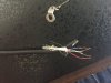
The black rubber I am referring to is the insulation that contains all four coloured wires, like in the image:tt_wire.JPG

I guess from what @cre009 is saying, I need to remove it completely.

Also, in the picture above, the little metal piece on top had all the original wires twisted in it (you can see them in the picture) with the ground as well I think. That piece is screwed underneath the pivot:

tt_pivot.JPG

Since the new wires are shielded and therefore thicker, they wont fit into the little hole I think. I should maybe keep the black rubber insulation to pass the new wires through it at that same place. As far as the ground goes, since the original was cut, what do you guys recommend as a replacement?
 
Clean the pins of solder, and the glue they used. i use sand paper. the wires may or may not go into the hollows, they weren't soldered in that way to begin with.
Not sure what you mean by 'black rubber", there should be just the 4 wires running through the tube
The black rubber I am referring to is the insulation that contains all four coloured wires, like in the image:View attachment 785901

I guess from what @cre009 is saying, I need to remove it completely.

Also, in the picture above, the little metal piece on top had all the original wires twisted in it (you can see them in the picture) with the ground as well I think. That piece is screwed underneath the pivot:

View attachment 785903

Since the new wires are shielded and therefore thicker, they wont fit into the little hole I think. I should maybe keep the black rubber insulation to pass the new wires through it at that same place. As far as the ground goes, since the original was cut, what do you guys recommend as a replacement?

That black rubber, and everything else has to go, you only want the 4 wires running through the tube. they then need secured in the small channel in the top of the pivot block. reattach that original ground system and attach a ground wire to the original braid after a short distance of braid. attaching a ground wire to that eyelet can cause the ground wire to break......I've had a few do that. the steel shield piece will take a lot of bending, tugging, etc. You only need to twist the arm wires after the pivot block. inside the tube, and in the pivot block they are shielded by the tube and block from RFI
 
For my deck I used cardas wire with no outside insulation. Not sure if the insulation will work well. Will it thread through the hole in the top plate?

You will need to do something with the ground wire. Initially I tried reusing the braided wire for my ground with the same connection to the back of the tonearm but eventually swapped to another replacement black insulated wire as part of my effort to reduce a tiny residue of buzzing. Never have solved that to my complete satisfaction.
 
Ok, I've resoldered the receptacle. I probably dont have the best tools for this (my solder iron is a little too big for these minuscule pins/wires by the look of it) and given the fact that its my first time soldering anything, I hope it will be ok. I'm assuming since the original wires didnt have any insulation on them, it wont be a problem that the wire are close or even touching near the receptacle?

tt_receptacle_rewired.JPG

I managed to get the receptacle back into the tonearm after making the two side dents a little deeper with the soldering iron as suggested in the link posted in the first posts.
 
Just saw on that page that the guys used some heat-shrink tubing for the receptacle wiring, is it worth it? Not sure my soldering is good enough so the wires never touch each other in the receptacle area...
 
Just saw on that page that the guys used some heat-shrink tubing for the receptacle wiring, is it worth it? Not sure my soldering is good enough so the wires never touch each other in the receptacle area...

I personally use shrink tube, if for nothing else than giving a bit more strength to the joint
 
I personally use shrink tube, if for nothing else than giving a bit more strength to the joint
Yeah I think I should use it too. Do you remember what size/ratio of shrink tubing you used?

Thank you so much for your help so far by the way :)
 
Is it normal that the metal T bar underneath is right under the hole where the tonearm wires have to pass through? It looks normal as the tonearm shaft right in the center of its plinth hole, what bothers me is that the space between the T bar and the plinth is quite narrow and I'm worried the wires might get damaged over time. Should I lower the suspension? The platter is about 1/4" higher than the plinth when everything installed (without vinyl).

IMG_5623.JPG
 
Not on an XA but on a Dual 506-1 I replaced the "built in" cable with a Mogami WR-06 cut down to about the stock length. I used that cable because it's relatively small so doesn't look out of place but still has low capacitance and good shielding.
 
There should be around 4mm clearance from the bottom of the platter and the top plate. I use a hex key for testing the clearance is the same around the deck and that the platter is level.

The position of the hole in the top plate relative to the tbar is normal which does make arm wire installation a bit fiddly.
 
platter distance from top plate is 1/8" min, 1/4" max. where the arm wires run on the bottom side of the top plate, above the subchassis they should be covered with tape
 
I finally finished the tonearm rewiring. I had to redo it all over again because as I had ordered a foot long of wiring, it wasn't long enough. I somehow thought I was buying a wire with a specific length for the XA as there was no unit beside the item on the parts connexion site...

Oh well, I did it with 2 foot long wires now and I got it done. BUT, the headshell is now tilted on the left and not even with the vinyl. I mean that the left side (when looking it from the front) is closer to the vinyl than the right (it even touches it when spinning) and the back side of the headshell is lower than the front. I reinstalled the receptacle in the 2 grooves, red mark on top.

Anyway, do you guys know how to even the headshell out?

twisted.jpg
tilted.jpg
 
You might be able to rotate the armtube some at the overhang set screw. It's possible the arm tube got bent a bit wrasslin the socket out of the tube.
 
Thanks, I managed to get it a little more even with basically the same move I was making when trying to remove the receptacle in the first place. Unless I misunderstood there is not really any adjustment to be made at the overhang screw since there seems to be only one tube position that will allow the screw to fit in the tube :idea:. Now it is, I think, at an acceptable level but still a little bit lower on the left, does it make sense to unscrew a tiny bit the right headshell screw?

On the other axle, the bigger problem is that the cartridge now is so low that the middle sometimes touches the record. It is the cartridge that came with the TT when I bought it, a SANSUI SN-P313 needle on a cartridge that I cant identify. Since the rear of the headshell is lower but by a very very tiny bit (from picture I saw of other XA, it looks normal), what can cause this?
 
check the tonearm with a straightedge, you may have bent it slightly when R&Ring and need to tweak it back.

I see in your pic that it does appear to be low in the rear. If the arm tube is not bent you may have to angle-shim the cart in the headshell as described in the manual.

It may just be the pic, but it looks like the cart is slightly angled in the headshell as well, should be parallel and then Marc M recommended an overhang of 16.5mm which is where I set mine and have had no complaints with the sound of mine.

http://audiokarma.org/forums/index.php?threads/stupid-question-setting-ar-xa-stylus-overhang.644916/

Which made me think of something. Maybe I should make my own overhang "gauge" in CAD and print it out, easier than flipping the headshell over and measuring to the pivot with architect's scale...
 
If you ever have to transport the table again, place heavy cardboard between the sub chassis and base plate then zip tie the chassis to stop it bouncing around. Later models had transport screws so the zip ties aren't needed. Saves the tonearm wires being damaged by the sub chassis. It's also a good idea to tie the tonearm down to the rest. I sent one on a 1200 km journey across Australia like this and it arrived safely at the other end. Removing the outer platter helps too. I did a short trip the other day and got lazy. Heard the platter shift half way home. Lucky it didn't take out the tonearm and cart. Lesson learnt.
 
Back
Top Bottom