• The move to the new server is done. There are some software and database maintenance updates in process. This has us passing the hat around to help out. We appreciate any donations. Seriously, even a dollar helps. The payment page may be found here - https://www.audiokarma.org/support.html

Ariston rd-40 board recap

I don't think so because you said 45 seems to play fine, but it certainly doesn't hurt to lube the motor (light oil, like sewing machine oil) after many decades.

Some DC servo motors have their speed controller built inside the motors, some others have their speed controller ouside of the motors. In the best DC servo motors there are coils and magnets inside the motors that generate a signal (pulses) that informs the speed controller about the actual motor speed. That controller then adjust the motor coil current to maintain proper speed. The Technics SL-20 and SL-23 are good examples of this kind of motor-controller set-up. I mention these models because I know (I made the schematic once I had one myself) that the Ariston RD11E was built with these Technics motors. Judging by the board you posted on post#1, I don't think you have this set-up.

In the cheapo DC-servo motors, the speed regulation is based on the back electromotive force (voltage) generated by the motor itself as it gain speed. An external regulated supply provides a voltage (different on 33 or 45) to the motor, that is dependent of the current drawn by the motor. These motors are more common on cassette decks that turntables. For good reasons, because these motors have poor speed regulation by comparaison the the first ones. Judging from your board, I think this is this kind of motor-contoller that you have.

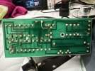
If you can take good resolution pictures of your board, one from the top and one from the copper side, we could possibly make the schematic of this board and find a solution to your speed issue. Maybe by altering the value of a resistor in series with the speed trim pot.

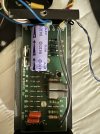
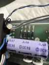
About the capacitors, what I see are good quality capacitors (for the small ones) that usually never need to be replaced. The larger one is the main filter for the DC power supply. Replace that one (2200uF/25V) by a larger one (4700uF/25 or 35V). Axial capacitors are more difficult to find and usually more expensive than radial capacitors. Most of the time I replace them by radial capacitors that I fix on the board with hot glue.

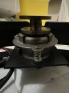
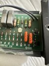
Here some photos, I hope it helps. Please let me know. Thanks! IMG_3898.jpegIMG_3894.jpegIMG_3895.jpegIMG_3896.jpeg
 
From what I can see in your pictures, I think that you should set the external pitch controls in mid position. Then, adjust the 33 speed with the internal calibration trim pot VR1. Then, adjust the 45 speed with the internal calibration trim pot VR2. After those adjustments, you should have the correct speed when the external pitch controls are in mid position, and approximately the same adjustment range (say +3% and -3%) for each speed. If the internal calibration trim pots are not set properly you will have unequal adjustment ranges with the external pitch control. For example you might have +1% to -5% on one speed. You might be unable to adjust the speed at the correct value if the internal trim pot is too far from the ideal position.
 
From what I can see in your pictures, I think that you should set the external pitch controls in mid position. Then, adjust the 33 speed with the internal calibration trim pot VR1. Then, adjust the 45 speed with the internal calibration trim pot VR2. After those adjustments, you should have the correct speed when the external pitch controls are in mid position, and approximately the same adjustment range (say +3% and -3%) for each speed. If the internal calibration trim pots are not set properly you will have unequal adjustment ranges with the external pitch control. For example you might have +1% to -5% on one speed. You might be unable to adjust the speed at the correct value if the internal trim pot is too far from the ideal position.
Thank you! The same was recommended at another forum. So I tried it today.

I have tried turning VR1 and VR2. So VR2 does as supposed. It is connected with 45rpm potentiometer regulator and by turning I can play with speed considerably. BUT VR1 has no effect on 33rpm, turning it changes nothing.

any good advice where to look next? Thank you.
 
You might have a solder bridge at VR1, or VR1 is defective. In your second picture, post #22, it looks like the wafer of VR1 does not make contact with the "horse shoe" resistor. Is it an illusion?
 
You might have a solder bridge at VR1, or VR1 is defective. In your second picture, post #22, it looks like the wafer of VR1 does not make contact with the "horse shoe" resistor. Is it an illusion?
You are genius! Bingo! Indeed it didn’t make contact. Not sure how it happened. When I fixed it it works now as it should. No need to change capacitors or resistors now. Thank you!
 
Back
Top Bottom