• The move to the new server is done. There are some software and database maintenance updates in process. This has us passing the hat around to help out. We appreciate any donations. Seriously, even a dollar helps. The payment page may be found here - https://www.audiokarma.org/support.html

AT-LP120XUSB

And the EXACT same thing happened–passive speaker was “crackly”. Am I doing something wrong? Too big a coincidence. I'd appreciate any thoughts.
Did you make sure the turntable's built-in pre-amp is turned on? (Set to LINE rather than PHONO.)
 
Yep. I did. This is a very strange problem. The powered speaker is fine, but the passive one is crackly, like a bad connection. But I checked it 10x. The connection is fine. There must be something I'm doing wrong. The exact same issue with 2 different brands of speakers is beyond unlikely.
 
. . . The thing that interests me most is the "improved" preamp. First, is it really improved, and second, if it isn't, have they at least rewired it to take it completely out of the signal path when it's switched off?
AT's website had a recent question about that. Their answer, in part, was:

"All Audio-Technica turntables have an inductor in series with the output and a capacitor from the output to ground in both phono and line out modes. These components are necessary to ensure the turntables comply with CISPR/CIS/I Electromagnetic Compatibility standards. These components are what people are referring to when they say the preamp is not 'completely' bypassed in phono mode. In actuality, the entire active portion of the preamp is bypassed and the output from the tonearm goes directly to the RCA outputs with only these two passive components left in the signal path." https://www.audio-technica.com/cms/turntables/60fd97f6023195fd/index.html
Funny they mentioned "old" LP-120USB in particular... There had been a solid evidence on how all these components affect the sound quality, and how indeed removing them makes the output sound brighter. Not necessarily better or worse, just different. Remember, "the beauty is in the eye of the beholder" ... or in this particular case, ears.

On a side note, I wonder what sets LP120 apart from all other tables, to require CISPR/CIS/I Electromagnetic Compatibility standards in the first place, since all the other models are wired directly & do not require filtering (including the first generation, AT-PL120)
 
A couple of questions for those who own an AT-LP120XUSB:

1. The tonearm height is not adjustable, but even at its lowest setting, its predecessor was still a bit tail up rather than level. Does this new model have the same issue? Have you tried, or do you think, that a taller cartridge body (e.g., a Grado Prestige) would result in the arm being level or even a bit tail down?

2. The new model has a ground wire whereas the older one did not. I've heard from Audio Technica that the ground wire is only needed when using the phono inputs on an amplifier or phono stage, that there should be no hum issues even without the ground wire when using the turntable's own phono stage and hooking it up to a line level input. Has anyone tried this to see if that is, in fact, the case?
 
Funny they mentioned "old" LP-120USB in particular... There had been a solid evidence on how all these components affect the sound quality, and how indeed removing them makes the output sound brighter. Not necessarily better or worse, just different. Remember, "the beauty is in the eye of the beholder" ... or in this particular case, ears.

On a side note, I wonder what sets LP120 apart from all other tables, to require CISPR/CIS/I Electromagnetic Compatibility standards in the first place, since all the other models are wired directly & do not require filtering (including the first generation, AT-PL120)
I don't think it's "funny" that AT made particular mention of the LP120-USB; after all, that model was specifically addressed by the person posing the question.

And is the LP120 different from other AT turntables? AT's answer in their Q&A section said, "All Audio-Technica turntables have an inductor in series with the output and a capacitor from the output to ground in both phono and line out modes. These components are necessary to ensure the turntables comply with CISPR/CIS/I Electromagnetic Compatibility standards." Sounds like all their models, at least those with both phono and line out modes, should be the same in this respect.
Except they're not... AT-LP5 (despite having internal preamp) is wired directly into the preamp (or phono input, depending on the switch position) without anything else in between. Same thing with AT-PL120 (the first version of LP120, which had a different preamp, without USB connection). Ironically, PL120 also had working Anti Skate right from the beginning, so only Audio Technica (or maybe Hanpin Electron) knows the true reason for not keeping PL120 in production as it was & "downgrading" to LP120. What I /do/ know is that LP120 came in (at least) 5 different generations, editions during its 10yr production:

1st gen featured the initial release, AT-PL120 unit but without USB feature. It had a working AS mechanism, and came with AT ATP3 cartridge, mounted on a standard "Technics" type silver headshell.

2nd gen featured the whole new approach - the unit is now called LP120 USB, which obviously has USB output. As such, it was given a whole new preamp, which (as of this model) had filtering across the tonearm signal. Also, I believe some folks reported the motor (pulsation) problems on this particular generation, along with warped platter. Cart remained to be the same as with PL120, ATP3 on a silver headshell.

3rd gen featured the change in cartridge choice, ATP3 was replaced for AT-95E (0.4x0.7mil), but the headshell remains to be the same as before. Some issues were addressed (pulsation, or maybe the warped platter, I honestly can't say for sure), but the AS still doesn't work OK.

4th gen featured the new color choice (black), known by the name of AT-LP120USB BK. Don't know about other changes (if any), but the Anti Skate still doesn't work OK.

5th gen (final one, maybe?) featured several upgrades in the layout... Anti Skate was finally repaired, "upgraded" as they say, to the same specs as "PL-120" & all other Hanpin clones such as Pioneer PLX500 for example. Also, the included AT-95E cartridge (or rather, the stylus) is now upgraded to a better spec (0.3x0.7mil), and the actual cartridge is mounted on a lightweight aluminum headshell (AT-HS10, colored either black or silver, depending on the unit itself, but ONLY for European-sold models). Those HS10 headshell units were given a new name, AT-LP120USBHC & AT-LP120USBHC-BK for black unit.

 
Except they're not... AT-LP5 (despite having internal preamp) is wired directly into the preamp (or phono input, depending on the switch position) without anything else in between. Same thing with AT-PL120 (the first version of LP120, which had a different preamp, without USB connection). . .

Are you sure about the AT-LP5? On AT's website, their Q & A section for that model also answered a question about the built-in phono stage. That answer also said "all current Audio-Technica turntables have an inductor in series with the output and a capacitor from the output to ground in both phono and line out modes," but the explanation went on to give this added information:

". . . The inductor and capacitor are in the circuit to prevent EMI from getting into the audio. The USB chip clock is always running and these components are used to block any undesired signal generated by the USB chip and / or clock. The capacitance is 100 pF, resistance is 600 ohms, and frequency is 2.6526 MHz."

Since the PL120 did not have USB, perhaps there was no "undesired signal" that needed to be blocked.
 
Last edited:
Are you sure about the AT-LP5? On AT's website, their Q & A section for that model also answered a question about the built-in phono stage. That answer also said "all current Audio-Technica turntables have an inductor in series with the output and a capacitor from the output to ground in both phono and line out modes," but the explanation went on to give this added information:

". . . The inductor and capacitor are in the circuit to prevent EMI from getting into the audio. The USB chip clock is always running and these components are used to block any undesired signal generated by the USB chip and / or clock. The capacitance is 100 pF, resistance is 600 ohms, and frequency is 2.6526 MHz."

Since the PL120 did not have USB, perhaps there was no "undesired signal" that needed to be blocked.
True, I never had the opportunity to peek inside, but judging from the community feedback on LP5, it was said that it sounds better, "cleaner" & brighter than LP120... :dunno:

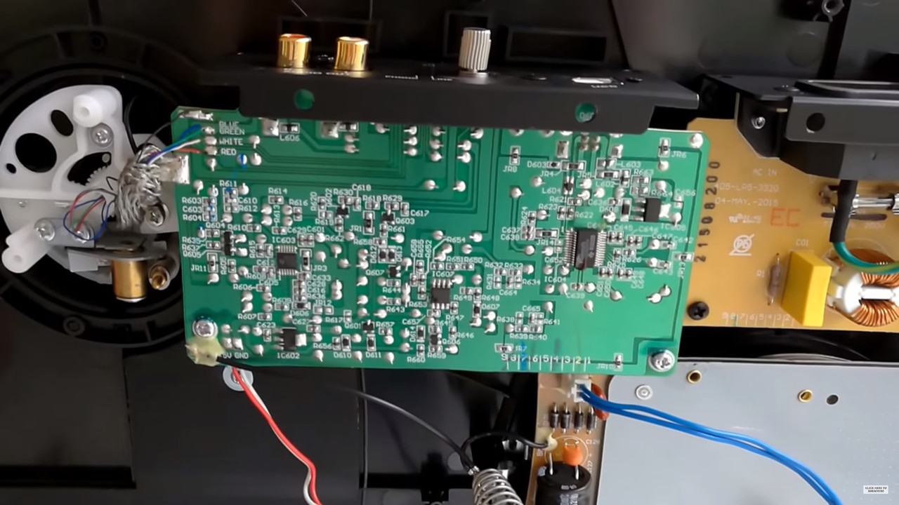
Here's a pic of the internal preamp (SOURCE), see if you can figure it out... From what I can tell, there is no filtering in this one, at least none that I can see, without flipping the board over and/or probing the terminals with my meter:
 
True, I never had the opportunity to peek inside, but judging from the community feedback on LP5, it was said that it sounds better, "cleaner" & brighter than LP120... :dunno:

Here's a pic of the internal preamp (SOURCE), see if you can figure it out...
I'm afraid I wouldn't know one part from another unless they were in labeled bags. I watched a video (link below) on removing the preamp from an LP120, and there is an inductor labeled L606 in that video that the presenter said was in the signal path. There is a part labeled L606 in the picture you posted, so maybe that's doing the same thing. We can't see the whole board, and I'm no expert in following the signal path like the guy in the LP120 video was doing.

In any event, I tend to just go by what the manufacturer says about their design; I figure if they say all their models have that inductor and capacitor in the signal path to block the undesired signal from the USB chip and/or clock, then they're likely telling the truth. I still think it's unfortunate that so many turntables on the market are available only with these built-in preamps and USB features. I know I'd be happier if they would offer the same 'tables without the extra electronics, particularly the USB (which I can't imagine ever using) if that's what's necessitating those two parts in the signal path, but the manufacturers likely know their market better than I do. The good news is that these turntables are available at affordable prices and most people seem very happy with the sound they're getting.
 
AT's website had a recent question about that. Their answer, in part, was:

"All Audio-Technica turntables have an inductor in series with the output and a capacitor from the output to ground in both phono and line out modes. These components are necessary to ensure the turntables comply with CISPR/CIS/I Electromagnetic Compatibility standards. These components are what people are referring to when they say the preamp is not 'completely' bypassed in phono mode. In actuality, the entire active portion of the preamp is bypassed and the output from the tonearm goes directly to the RCA outputs with only these two passive components left in the signal path." https://www.audio-technica.com/cms/turntables/60fd97f6023195fd/index.html

But the output is still colored by those components. So the answer would be kinda/sorta...
 
jrtrent has it correct. The series choke and chip cap to ground form a resonant circuit . Knowing the inductance of the choke and the 100pf capacitor would make it easy to figure out the resonant frequency. Might be to filter out usb radiation or keep strong am radio stations from being picked up by the cartridge. Appears it would not have any effect in the audio passband. FS = 1 over 2 pi times the square root of inductance times capacitance. I believe your frequency of 2.6526 MHZ. but would like to prove it. Thanks for the info.
 
Speaking of which... This is kinda off-topic, but still somewhat relevant to the recent discussion.

I was talking to a guy earlier today, who just removed preamp from his LP120 & swears how the audio quality improved several times. Which made me think ... I'm not ready to rip out the internal preamp & give up on "USB" feature, especially if & when I decide to sell my LP120 down the road. In fact, being "USB" is one of its key features, which would essentially reduce unit's value down the road. So, I did some Googling & found out THIS article.

It kinda confirms my suspicious, about being able to "bypass" rather than to yank out everything. Because, I'm personally leaning towards "Method #1" - bypassing the Low-Pass filter & keeping the preamp (and USB circuitry) in place. In fact, everything remains the same, except for the two inductor coils & capacitors. Obviously, the two caps would have to be removed, but just like the picture suggests, I would use a short piece(s) of wire to form a jumper across "L606" & "L607". As I already mentioned, C631 & C632 are the ONLY two components which would have to be removed from the board. No need to modify anything else, including the ground wire, or even the RCA jacks.
MEthod-1-03.jpg


What are your thoughts on this method, did anyone try something like this before? In the worst case scenario, it is always possible to remove the entire board & finish it off with standard method, but I would rather keep it "stock", or at least as close to stock as possible.
 
Last edited:
It sure beats cutting out the board and will accomplish the same thing. I never modified my LP120usb because it sounds fine the way it is now and the standard method is BS anyway. When removing c631 and c632 always use fine solder wick and low heat to gently remove as much solder as possible. Then use needle nose pliers to give a light twist on the body and they should come out clean. If you want to reinstall them you may need a third hand to keep them in position or tack glue them back in place before soldering. The jumpers on L606 and L607 are easily desoldered. As far as I know you're the first one to put this method in print.
 
It sure beats cutting out the board and will accomplish the same thing. I never modified my LP120usb because it sounds fine the way it is now and the standard method is BS anyway. When removing c631 and c632 always use fine solder wick and low heat to gently remove as much solder as possible. Then use needle nose pliers to give a light twist on the body and they should come out clean. If you want to reinstall them you may need a third hand to keep them in position or tack glue them back in place before soldering. The jumpers on L606 and L607 are easily desoldered. As far as I know you're the first one to put this method in print.
I was even thinking of jumping the two inductors, using a short piece of wire. Leaving L606 & L607 in place, but fully bypassed.

Not sure if that would affect the circuitry though, but it would be (even) easier to remove the mod, if & when necessary. C631 & 632 would be difficult to fix back in place though... I remember soldering SMD capacitor once, on a very old PC 3D graphics accelerator card and it was a PITA to say, at least.
 
. . . It kinda confirms my suspicious, about being able to "bypass" rather than to yank out everything. Because, I'm personally leaning towards "Method #1" - bypassing the Low-Pass filter & keeping the preamp (and USB circuitry) in place. In fact, everything remains the same, except for the two inductor coils & capacitors. . .
The author of that article was unable to try method 1 due to his having caused some damage, so we don't know if it would have worked for him. He also said, "I have not investigated it, but I believe that the USB circuitry is only active (powered) when the turntable is connected to a computer with a USB cable. So a potential problem with digital noise might only be present when the turntable is used to digitize records. When the USB circuitry is active." Audio Technica, however, stated, "The USB chip clock is always running and these components are used to block any undesired signal generated by the USB chip and / or clock." If you're going to bypass the parts that block that unwanted signal, do you have a way to be sure the USB stuff won't be running?
 
The author of that article was unable to try method 1 due to his having caused some damage, so we don't know if it would have worked for him. He also said, "I have not investigated it, but I believe that the USB circuitry is only active (powered) when the turntable is connected to a computer with a USB cable. So a potential problem with digital noise might only be present when the turntable is used to digitize records. When the USB circuitry is active." Audio Technica, however, stated, "The USB chip clock is always running and these components are used to block any undesired signal generated by the USB chip and / or clock." If you're going to bypass the parts that block that unwanted signal, do you have a way to be sure the USB stuff won't be running?
Right, I know... Which is exactly why I said that (in worst case scenario) it's always possible to remove the entire board & finish it off with standard method. I was previously working on computer components (I collect & restore old, vintage computers for fun), so I have some experience with removing & soldering SMD components. Not much, I prefer through-hole design for obvious reasons, but sometimes it just isn't possible... Removing SMDs is straightforward job, I honestly don't expect much (or any) problems with that. Tiny blob of solder on each side, heating it up & "pushing" the SMD out of place. Restoring it back however is a lot more difficult, especially if you don't have the right equipment & a steady hand.

And no - the idea behind jumping (rather than removing entirely) was only because to leave USB in place, fully operational. I'm actually curious to see, or rather hear how much of this "unwanted signal" is leaking into the outputs. I was hoping that maybe someone here already tried the same method, and would hopefully give me a tip or insight on how to proceed.
 
My last post described the correct way to remove SMD components. If you have your own ideas you'll probably damage the board or rip up the foils. If you don't feel comfortable or confident doing this type of work don't even attempt it.
 
With all due respect why bother hacking these units?
Bought new they are under guarantee for 12 months minimum,second hand 30 days to 3 months at least in this country and I suppose everywhere else on this planet,so if its not up to par return it and get your money back.
I used to chip Xboxes to vastly improve their performance and to get that flexibility from a games console there was no other option available,in the case of these modern tables at the price point there is.
 
My last post described the correct way to remove SMD components. If you have your own ideas you'll probably damage the board or rip up the foils. If you don't feel comfortable or confident doing this type of work don't even attempt it.
I have a 30W "amateur-class" soldering iron, which can only generate so much heat, comparing to more powerful & professional models. We'll see, I'm not afraid to crack it open (and remove SMDs), but I am hesitating to do this mod, especially since no one else attempted it before.

With all due respect why bother hacking these units?
Bought new they are under guarantee for 12 months minimum,second hand 30 days to 3 months at least in this country and I suppose everywhere else on this planet,so if its not up to par return it and get your money back.
I used to chip Xboxes to vastly improve their performance and to get that flexibility from a games console there was no other option available,in the case of these modern tables at the price point there is.
Because of what people are saying... Almost every single person who removed the preamp claims how the high end sounds much better, some are even saying that it sounds 10x better than it used to *shrug* IDK, since I haven't modded mine yet, I can't either confirm or deny this.

LP120 units here in Europe have a 2yr warranty period. Since I bought mine at the store (licensed distributor for Audio Technica, among other brands) I also have access to free service & repairs, if necessary. Which is not the case (I think?) for units obtained online, though ebay & similar. Either way, I still got 5 months of warranty left, as it was bought on December 2017. But regardless of the warranty, I'm not willing to remove the preamp due to USB feature. So, bypassing L606 & 607, and removing C631 & C632 seems like a reasonable compromise, at least in theory.
 
Back
Top Bottom