• The move to the new server is done. There are some software and database maintenance updates in process. This has us passing the hat around to help out. We appreciate any donations. Seriously, even a dollar helps. The payment page may be found here - https://www.audiokarma.org/support.html

AU222 Single Channel Stereo, Smoking plus new Bass Potentiometer

blue_cat

New Member
Hi all,

I picked up an AU222 last week and have experienced a few issues. I'm okay with a soldering iron and have performed successful single capacitor replacements before now but I need some help with troubleshooting and guidance.

1. Single channel stereo output
During testing only one of the channels was outputting sound in Stereo. In Mono, both channels output okay but lots of crackles and pops when adjusting dials and making changes. The sound also seemed a little muffled to my ears. I thought a clean might fix it but before i could clean it, it started smoking as I was listening to a record in mono through both speakers!

2. Smoking
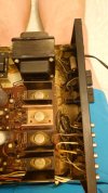
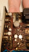
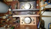
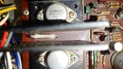
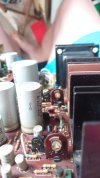
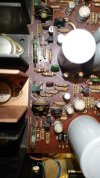
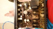
From what I can tell it's smoking from a small resistor between two of the heatsinks, one of which was weirdly copper rather than black. The manual suggests its a 1W 0.5Ohm wirewound which are cheap enough, but it seems like a symptom rather than the cause. Could this have been because I was in Mono and one channel was working overtime? Any ideas what the reason for this could be?
Should i be considering a recap or at least buying the caps to do so methodically? I priced up a full recap (including 4 power transistors) at ~£45.
WhatsApp Image 2024-07-04 at 15.27.28 (5).jpegWhatsApp Image 2024-07-04 at 15.27.27 (1).jpegWhatsApp Image 2024-07-04 at 15.27.27.jpegWhatsApp Image 2024-07-04 at 15.27.28 (6).jpegWhatsApp Image 2024-07-04 at 15.27.27 (2).jpeg

3. Bass Control Potentiometer
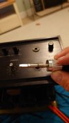
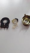
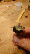
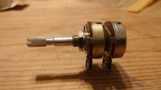
Unfortunately, whilst removing the faceplate to give everything a good clean including the pots etc. the knobs were quite stiff and one in particular was VERY stuck on. As it turns out, someone used superglue to stick it to the spindle and the knob and spindle came out of the pot as one! I've since detached the knob from the spindle with a fair amount of effort.
I'm assuming repair isn't really feasible but I don't know where to look to find a suitable replacement. I've seen smaller pots for sale online but presumably the pin layout and spindle length will be different. Any suggestions on how or WHAT to replace the pot with?
WhatsApp Image 2024-07-04 at 15.27.28 (4).jpegWhatsApp Image 2024-07-04 at 15.27.28.jpeg

I'm pretty devasted that my small first project amp is now looking not so small.

Any advice on how to proceed would be greatly appreciated!
 
Register to hide this ad
You have a beautiful amp there,well done.
Mind there is nothing in there that can’t be substituted, if needed .
Hard to find a pot-meter for the bass but if you measure right ,you might be lucky and find almost the right one in Mouser and with a small modification fit in.

Have you got the amp from Japan ? Where are you located? And are you sure that the voltage switch for the mains is setup properly for your voltage in your country?
 
With a little bit of surgery, you might be able to put the pot back together.
 
suggest you replace the bias trim pots as well and re calibrate to factory spec check the output and driver transistors for any shorts
 
Thanks all for the help so far! I'm from the UK and picked it up locally. I probably paid a bit over the odds for it, thinking it was working and might need a good clean and perhaps a little work. I'm happy with it though and expect it'll be a fun project, plus reviews are good and it's the perfect size to fit on my vinyl unit next to my GL75.

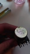
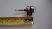
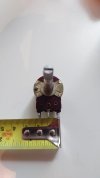
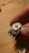
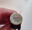
I took the pot off to take measurements, photos and have a look at the damage. From the back, it looks like an ALPS 100kOhmAX2 1.9 . I can't see anything similar except some eBay listings for pots removed from other Sansui Models but I don't think they're exact matches.
WhatsApp Image 2024-07-08 at 11.50.16 (4).jpegWhatsApp Image 2024-07-08 at 11.50.16.jpegWhatsApp Image 2024-07-08 at 11.50.16 (1).jpegWhatsApp Image 2024-07-08 at 11.50.16 (2).jpeg

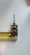
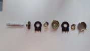
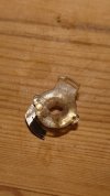
As I suspected, the spindle was centre punched to deform it around the plastic cams??, preventing removal. In pulling the spindle out, one of the cams has broken in half and the other will require the deformation reversed to get it back in. I'm feeling fairly confident that I can successfully repair it but I'll still have a look for a replacement in case the repair isn't as long lasting as I hope.

Before I repair the pot and refit for testing, any ideas on my issues 1 & 2. Stereo output and a smoking resistor? Will the general cleaning have fixed it (doubtful but hopeful)?

WhatsApp Image 2024-07-08 at 11.50.16 (7).jpeg


@quadmatrix suggest you replace the bias trim pots as well and re calibrate to factory spec check the output and driver transistors for any shorts
Do you mean the main bias pot with a front dial or do you mean the 4 internal ones below? The internal ones look so simple there can't be much to go wrong with them. I don't have an oscilloscope or variable voltage supply so I fear re-calibration would be difficult/impossible until I bought one.

WhatsApp Image 2024-07-08 at 11.50.17 (3).jpeg
 

Attachments

  • WhatsApp Image 2024-07-08 at 11.50.16 (5).jpeg
    WhatsApp Image 2024-07-08 at 11.50.16 (5).jpeg
    34.6 KB · Views: 10
  • WhatsApp Image 2024-07-08 at 11.50.17.jpeg
    WhatsApp Image 2024-07-08 at 11.50.17.jpeg
    28.4 KB · Views: 11
It turns out there's a Mouser office right next to my hometown so I'll give them a call to see if I can collect and save on postage. Hopefully it's not just an office and has stock :D
 
Thanks all for the help so far! I'm from the UK and picked it up locally. I probably paid a bit over the odds for it, thinking it was working and might need a good clean and perhaps a little work. I'm happy with it though and expect it'll be a fun project, plus reviews are good and it's the perfect size to fit on my vinyl unit next to my GL75.

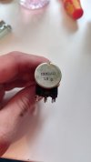
I took the pot off to take measurements, photos and have a look at the damage. From the back, it looks like an ALPS 100kOhmAX2 1.9 . I can't see anything similar except some eBay listings for pots removed from other Sansui Models but I don't think they're exact matches.
View attachment 3245907View attachment 3245910View attachment 3245909View attachment 3245908

As I suspected, the spindle was centre punched to deform it around the plastic cams??, preventing removal. In pulling the spindle out, one of the cams has broken in half and the other will require the deformation reversed to get it back in. I'm feeling fairly confident that I can successfully repair it but I'll still have a look for a replacement in case the repair isn't as long lasting as I hope.

Before I repair the pot and refit for testing, any ideas on my issues 1 & 2. Stereo output and a smoking resistor? Will the general cleaning have fixed it (doubtful but hopeful)?

View attachment 3245914


Do you mean the main bias pot with a front dial or do you mean the 4 internal ones below? The internal ones look so simple there can't be much to go wrong with them. I don't have an oscilloscope or variable voltage supply so I fear re-calibration would be difficult/impossible until I bought one.

View attachment 3245915
You really should change all the trimmers they are unreliable it’s possible your amp was way out of spec due to the trimmer and this contributed to the smoking resistor Bourns make some good replacements
 
I see that the pot I has the letter (C) marked on the back .
I know that (A) is linear and (B) is logarithmic but what is (C)? That might be an indication that the pot is working differently?
 
I assumed the C was a copyright, interesting if it denotes a different type from A and B. It would also mean I can't switch volume pots for bass control.

Presumably you mean the little blue Bourns sealed units with a screw on top. I'll definitely look into this when I come to order new stuff, if I can't find a cheap oscilloscope I'll have to see if my local hifi shop can do it.

I repaired the pot last night, glueing the cams onto the shaft. I think it went pretty well though unsurprisingly, it's not as smooth as the others. I think I saw a replacement last night but the shaft length was probably too short.

The shaft has to be cleaned up to get the cams on but without much use and not a mechanical function, it should be fine.
DSC_7891.JPGDSC_7892.JPGDSC_7893.JPG
DSC_7894.JPG
 
I see that the pot I has the letter (C) marked on the back .
I know that (A) is linear and (B) is logarithmic but what is (C)? That might be an indication that the pot is working differently?

The letter C in a circle on the back of he pot in question isn’t relevant to the type of taper employed by the bass and treble pots used in AU-222. If you look at the part number/ description in the service manual you will see that the bass abs treble pots are listed as 100kohm (A) with (A) being the taper type.

In the photo of the back of the bass pot a couple of posts above pertinent infipormation is “100kohmAX2”. So, 100kohm, taper A, dual, is what is meant. The arrow in the photo below shows the taper A indicated as part of the part number for the pot.

IMG_0473.jpeg

The C indicates reverse log (audio) taper.
That is the correct taper description for type C, but the pots in the 222 are either type A “Linear” (Bass and Treble), type B Log (volume) and type M,N for the balance (taper type for the M,N is a special type that is used in balance pots)

I hope this clears up any condusion regarding the pot taoer types utilised in the AU-222

Cheers
John
 
Last edited:
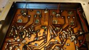
I had a look tonight and saw some black marks on the underside of the board. I thought it culd be heat damage but it came off quickly so quite possibly just flux.
DSC_7922.JPG
DSC_7923.JPG

I desoldered a couple of the transistors (TR806 and TR808 which gave readings of 0.643mV

The 0.5Ohm resistors that were smoking measured at 0.5 but V837 and it's twin were supposed to be ~64ohms and one measured 50 and the other 45. I guess they should be replaced.

Based on that I feel like I should go through and check every component systematically for tolerance but I'll start with the resistors.

Two of the Bias Trimmers started at 50kOhms and climbed to beyond 80kohms, the others stayed steady at 50ohms. Does this mean there's a capacitor inside the trimmer that's bad? There doesn't look to be room enough for one.

There also looks to be 2 diodes missing (D803 D804) from the board that are listed on the circuit diagram. Is that normal and what would the spec be if I need to replace. The manual just says SV2

DSC_7927.JPG
In better news, someone has offered me some Leak Sandwich 150 speakers and a NAD3010 for free
 
Last edited:
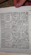
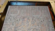
After struggling a little to identify pins last night, I thought I could use GIMP to overlay the circuit diagram onto a picture of the underside of the board. For a quick edit, it's not bad but the component names all need flipping manually (it would be better to do this before I flip and fit it to minimise warping and misalignment). I'll take better photos of the manual and the board this evening to see if i can get a better version. I'm sure it'll be a useful reference if I have to test everything on the board.
sansui au22 main board(circuit overlay).png
 
After not touching the amp for a while, I realised today that I misread the circuit diagram and tested the transistors from the working channel by mistake, probably because of the dark flux on the board .asking me think they'd gone bad.

Realising my mistake, I checked TR803, TR805 and TR807 and will double check my readings tonight. The resistance readings were crazy high in 10Mohms but I'll check voltage tonight.

EDIT: It came to me today that I can swap the paired transistors into the bad channel to see if the issue is resolved.

I also went through all the resistors last night (in circuit), all seemed okay. I took readings and will double check them against expecteds tonight.

For the single channel in stereo issue, could this just be the transistors or are there more likely culprits elsewhere? One of the capacitors on the head board (C605), looks a little brown down the side so I'm leaning towards buying a cheap combined component tester/ESR meter to check all the capacitors in circuit.

I found a dual channel oscilloscope for £45 which is on its way to use for bias and seeing other issues visually.
 
Last edited:
So I switched the output transistors and the other channel sounds great. The clarity in the sound is so good with each instrument clearly separated. I was listening to some Jazz and it felt like I was in the room listening to the music live, I'm not sure I've ever had that with an amp before. I'm not going to recap it if it's working but I have bought the ESR meter and oscilloscope socan diagnose as I experience issues.

Also, my repair to the bass pot seems to work okay , even if it isn't very smooth to turn.


To get both channels working, I'm just looking for replacements the transistors below
- 2SC815
- SSA539
- 2SC871 D.F.

I'm not sure on transistor specs and after searching they're either out of stock or not quite the same model number. I would appreciate any help and advice finding replacements.
 
I had to call Mouser UK to quote and after some back and forth, they told me that they were discontinued by the manufacturer and they didn't stock them.
There are some on AliExpress but I feel like the likelihood of fakes/wrong components is way too high
 
Just when I thought I was seeing the end of this, I went and did something stupid and need suggestions on where to start investigations.

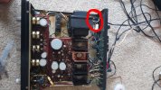
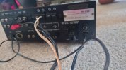
I managed to source some A539, c815 and c1845s to replace the faulty ones. Unfortunately, I thought the unit was unplugged with power off and I accidentally caught my hand on the mains in cable whilst taking off the metal case (red arrow for location). It was turned off but it wasn't unplugged ! A short sharp shock later and the main 2A fuse went and since then the once working channel is no longer working.

IMG_20240909_144641.jpgDSC_9017.JPG

I've since soldered in the replacement transistors for tr801,803,805,807 to the other channel in the hope it would spring into life but no such luck. But now that channel blows immediately too.

When I power it on I hear a short buzz and then the channel protection fuse goes and nothing.

I'm pretty disheartened but as I have the working NAD1030 to keep me going, I feel I should press on with getting this AU222 back to sounding beautiful. The brief period of single channel was so enjoyable I want to hear it in stereo, ideally with a QS100 for abit if fun.

Any ideas on where to start the investigation? I'm going to ask the seller if they have a pinout/datasheet for each of the transistors to confirm I've got the pinout correct.
Perhaps I can take voltages at points across the circuit?
I might try taking the transistors out and seeing if the problem remains.
I only have about 6 fuses remaining but will get some more ordered.
 
Back
Top Bottom