• The move to the new server is done. There are some software and database maintenance updates in process. This has us passing the hat around to help out. We appreciate any donations. Seriously, even a dollar helps. The payment page may be found here - https://www.audiokarma.org/support.html

Audire Forte250 Build

IMG_5024.jpegIMG_5023.jpegIMG_5025.jpeg
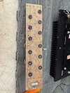
Crazy the HD hardware they used to bolt the outputs down.
I see where I could drill and tap to hold those drivers to the heatsink
 
Yes, probably easier to drill/tap, and the large threads have more strength than finer threads.
 
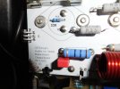
Any idea what that part is in the center. Cream colored and a single black strip.
Yes - it's a zero Ohm "resistor" used as a jumper wire. Audire used them in a lot of equipment, particularly preamps.

Most often they are used because they are easily machine-placed like other resistors. I am pretty confident Audire did not use parts placement machines, but using them was a holdover from Julius' work at NASA.
Wow. Never heard of a zero ohm resistor before.
 
Oh, just realized you were talking about the screws used to bolt down the outputs. Those must have just been what was available for those mounting studs. He used finer thread studs and bolts on other amps.
 
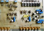
Here's an Andante preamp with a bunch of zero R jumpers.

These were used before 2 or more layer PCBs. You can see a mix of bare wire and 0 Ohm jumpers here.


AndanteBoard.jpg
 
You can't really see the pitch, but these transistor mounting studs and screws are finer pitch than what you see in your Forte 250.

These are new boards I designed to replace some original boards in a pair of Nobles that had been damaged by a bunch of parts catching fire. All without blowing the fuses!


GKTAudio_Audire_Noble_Boards.jpg
 
Last edited:
This was during reassembly of the Forte. I went with new drivers, new resistors on the entire output board, new diodes, new Zobel cap and resistor, new fuses. This amp had seen a lot of heat stress.

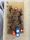
I also added insulating paper on top of the driver screws, since they are pretty close to the back of the input board.

The other channel is completed and partially visible in the rear.

GKTAudio_Audire_Forte.jpg
 
IMG_5021.jpeg
The fuse shows 5amp rating but that thick spiraled wire in it looks like 25amp, never seen anything like it.
 
Congrats on the Forte 250, @hamrules.

I've worked on about 16-17 Audire amps and preamps including a Forte which was apparently a late pre-production model.

Here are some suggestions. First, don't raise idle current to 35mA - keep it around 10-11 for now and check for crossover distortion, adjust upward to reduce/eliminate. Also, check heat sink temperature after 10 minutes of feeding an input signal sufficient for maybe 50wpc out into 8 Ohms. I suspect you may not as high as 35mA idle setting, which might cook everything. There is very little space inside this amp and the outputs are buried in there.

Looks like 6 output devices per channel? Same as the standard 125wpc version. Yes, I'd expect Julius raised the rail voltage to get there, something he did with MOSFET versions of some amps. I wouldn't be surprised if he used higher current/voltage output transistors - what are in your unit? Looks like the transformers in your unit are definitely different than the 125W version, and oriented differently.

Julius loved really stiff power supplies and used very high main cap values. If I recall, the pre-production 125W Forte had 80,000uF per channel - I can't recall the individual cap values but I ended up replacing them with slightly lower capacitance value higher voltage rated caps. Your amp has shorter caps. What are the values?

Not surprised by the MPQ7051 packages - he should have used them in a lot of his amps that ran rail voltages, even for the A versions. He had a lot of failures of the MPQ6600 over the years and ended up replacing them with matched discrete transistors with an aluminum tab glued across the tops. I pull all of the MPQ6600 out of any Audires I work on and replace them with super close-matched transistors and glue a copper strip across them with high heat epoxy. However, if yours still test closely matched, I'd definitely keep them, since they are much higher voltage-rated than the 6600.

Post more good photos as you move along with the work.
What kind of high heat epoxy if you don't mind. I see so many choices along with silicone adhesive types.
 
MG Chemicals 8349TFM. It is thermally conductive, flame retardant and good to 120C continuous, 200C intermittent, though these parts will never see that range. Much better heat transfer than silicone types.
 
And a pair in an Apt 1 power amp. They are close together so I just bond them both with the thermal epoxy.

GKTAudio_Apt_1_Diff_Pair.jpg
 
Thank you. I made a jig so I can assemble/glue a bunch at a time. A solderless breadboard also works.
 
Back
Top Bottom