


1960: These were heady times at Fisher Radio Corporation. Stereo was the rage, the power war was on, and innovations were appearing overnight. Fisher was well into the process of quickly making its brilliant pivot from an emphasis on "separates" to emphasizing its all-in-one line of integrated amplifiers and receivers. And, it was a company bent on making "firsts" in the industry. It was the perfect time and environment then for the introduction of the TA-800.
It's little brother (the TA-600) had been introduced a year earlier, and represented Fisher's first use of RCA's new high performance 7199 pentode/triode phase inverter driver tube. While otherwise conventional, the huge "first" of the TA-600 was its successful combining of a high quality full featured stereo integrated amplifier, with high quality independent AM and FM tuner sections, to allow for the reception of AM/FM stereo broadcasts. It represented the smallest Fisher footprint at the time for all the features it offered. Fisher however was always on the lookout for new technology that could improve it offerings, and it was coming fast and furious in those days.
One item of significant interest was the introduction of the 7591 by Westinghouse in 1958. This little power house packed at least twice the power of a 6V6 into the same size bottle. All of a sudden, an honest 60 watt (total) stereo power amplifier could be had for little increase in space than a 40 watt 7189 design occupied. Add to that, the development of reliable high voltage silicon rectifiers that make possible the use of low loss cool running voltage doubler power supplies, and you have the basis for Fisher to create another "first" unit -- which they did: when the 7591 was registered with the EIA in February of 1960, Fisher wasted little time in releasing the TA-800 that year as well. With the trade off in space requirements between the power amplifier and power supply sections basically being a wash then, Fisher was ultimately able to capitalize on the firsts it offered in the TA-600, and added to them greater power output in the TA-800, using the same basic physical space as it's little brother occupied. With more power, new tubes, and new SS power supply, and it was another Fisher First! -- something Fisher took very seriously.
With that quick backdrop in mind then, it's now 57 years later, and I've had one of these babies delivered to me personally by AKer Rob Thomas for restoration. You can find Rob's original thread on this unit here:
http://audiokarma.org/forums/index.php?threads/ta-800-back-from-the-shop.769372/
In view of the anticipated work the unit will need, and the relative rarity of these units as compared to other Fisher stereo receivers, I thought it best to start a new thread on the restoration of the unit. It is surely a thing of beauty.......... but what a sad sack it is operationally for a Fisher! Consider that as received:
1. The AM Tuner doesn't work.
2. The FM Tuner doesn't work.
3. The Left Channel doesn't work.
4. The Balance Control is weird.
5. The center two output tubes try to red plate.
6. The AC power switch has failed.
Oh, and the AM Bandwidth/volume control/AC power switch assembly is so loose and sloppy that wires connected to it have broken off, as well as from the Balance Control next door as well. It appears that at some point in the past the volume control assembly was partially removed in an attempt to fix the power switch. Since the original switch is still in place, that effort was clearly unsuccessful. But when the assembly was reinstalled, wires to the loudness switch that were cut for its removal were never reattached, and the assembly was so sloppily reinstalled that wires either broke off from the movement of the assembly with use, or were simply never reattached. It's a mess to be sure.
When I receive a unit, I first do an initial assessment by going completely through it and verifying the operation (or not) of every feature. Then, I troubleshoot to find out what the problem is for each concern noted. That's because there are problems that a simple recap restoration effort will not resolve. The assessment then allows me to determine what will be addressed by the restoration, and what needs to be repaired separately. Finally, all the tubes are performance tested so that then, along with the results of the assessment, a true picture of the restoration work required can be developed.
That process played out well with this unit, as with troubleshooting, it was found that:
1. While the AM tuner had two very weak tubes (causing that section to take notably longer to start working because their emission was so poor), the real problem of no reception was due to the loop antenna having no continuity. Some time in the past, the plastic mount for the loop antenna was broken. When that happened, one of the leads from the coil to the connecting terminals on the assembly was broken as well. Then, when it was glued back together, the glue accidentally covered up the broken lead so that the damage done was hidden. I was able to chip away at the glue, retrieve the lead and reattach it, and then able to pick up one of my late night listening stops: Radio Toronto, bad tubes and all.
2. The dead FM section was found to be due to an open R29, a 68K resistor supplying screen grid power to the 1st IF amplifier stage. But while replacing it, and even accounting for two poor tubes in the FM RF section, reception was still very weak, with no deflection of the eye tube bars. That was traced to a defective Z3 IF Limiter Coil, that had the classic silver mica disease. That too has been successfully repaired, but even then, performance was still notably poor. The final issue identified was a very poor alignment of the entire IF strip, likely the result of some previous service effort that was attempting to "fix" the FM problems by aligning that section while Z3 was defective. With those issues resolved, other than a weak presenting (worn out) FM eye tube, the FM section now operates normally with plenty of sensitivity in spite of the weak RF tubes.
The resistor would have been caught during the general component check of the restoration process. But replacing it and the bad tubes still would have resulted in poor performance of the section. Troubleshooting to find the defective limiter coil and poor alignment completed the picture for the total work required to bring the FM section back to life.
3. The dead left channel was due to a shorted C114 coupling cap in the tone control amplifier stages applying over 100 vdc across the volume control. This saturated the pentode section of the left channel driver tube, causing no amplification of the stage. The normal restoration process will resolve this issue.
4. The weird Balance Control operation is due to broken/shorted wiring to the control. With the other broken/severed wires to these controls, the physically loose assembly of the volume control, and the defective AC power switch, these controls will both be completely removed from the set, and cleaned up, tightened up, and repaired accordingly as a separate function apart from the normal restoration process.
5. The center two output tubes are new TS reissues, which have been well established to require greater bias voltage to establish normal current flow. When this is coupled with a still remaining selenium rectifier in the DC Heater/Bias Supply, red plating of these particular tubes is inevitable. This will also be addressed with modifications outside of the standard restoration process.
The items that were repaired as part of the initial assessment were done to present the best overall picture with regards to potential outcome of the completed project to Rob. After all, FM IF transformers that can't be fixed or an AM loop antenna that can't be fixed would change to course of the project considerably, either in outcome, or required expense and effort to achieve a desired outcome.
With all the potential deal killers checked, assessed, and/or resolved then, the project was given permission to move forward so that the actual restoration could begin. As a result, tubes have now been ordered from Jim McShane, power supply caps ordered from AES, and I've reached out to Mark Oppat for a new power switch, although I'm still waiting to hear back from him.
The standard recommendations of adding an AC line current limiter, output cathode resistors, screen stability resistors, and converting the old selenium rectifier to silicon will also be done. In addition, individual bias controls are being added, and Rob has also asked me to investigate the installation of EFB(tm) in this unit as well.
So with the stage set, it's off to the races. A few pics are presented to get things started, and then I'll make updates along the way as progress happens, parts arrive, and modification plans develop.
Dave
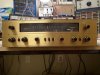
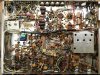
BELOW: Early Fisher gear is some of the nicest looking gear!
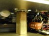
BELOW: The glue has been chipped away, the bottom coil lead retrieved, and reconnected to its terminal repair the antenna loop.
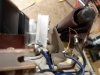
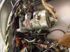
BELOW: Removing the offending FM IF Limiter Transformer.

BELOW: Removed from the set.
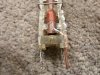
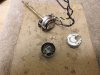
BELOW: Inside the transformer, the coil's B+ lead was carefully unwound from its connection terminal, since it was the shunt resonant cap across the coil that was diseased.

BELOW: .....and connected to a new terminal installed in the unused 4th terminal location. This way, connection to the coil could still be made, but the old resonant cap in the transformer would be out of the circuit.
BELOW: Reinstalled, good as new. Note the new silver mica resonant cap installed between the new terminal and the one opposite to it. All the connections originally installed on the third terminal have now been moved over to the new terminal, and the old terminal is bent over underneath the new resonant cap.
The transformer now produces a very sharp and defined peak as it should when aligned.
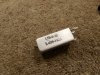
BELOW: This 68K resistor (R29) shows infinite resistance. It is simply open. Not burned open. Just open. I have seen this before with Fisher and other manufacturers as well. Every now and then, they would have to source what history has now shown to be a lower quality piece to maintain production levels. It was not uncommon for resistors of this type manufacture to go completely open as this one did.
BELOW: It was replaced with this NOS piece taken from storage that was held in a vacuum sealed bag.
BELOW: Broken loudness tap wires.
A couple more pics to follow.
It's little brother (the TA-600) had been introduced a year earlier, and represented Fisher's first use of RCA's new high performance 7199 pentode/triode phase inverter driver tube. While otherwise conventional, the huge "first" of the TA-600 was its successful combining of a high quality full featured stereo integrated amplifier, with high quality independent AM and FM tuner sections, to allow for the reception of AM/FM stereo broadcasts. It represented the smallest Fisher footprint at the time for all the features it offered. Fisher however was always on the lookout for new technology that could improve it offerings, and it was coming fast and furious in those days.
One item of significant interest was the introduction of the 7591 by Westinghouse in 1958. This little power house packed at least twice the power of a 6V6 into the same size bottle. All of a sudden, an honest 60 watt (total) stereo power amplifier could be had for little increase in space than a 40 watt 7189 design occupied. Add to that, the development of reliable high voltage silicon rectifiers that make possible the use of low loss cool running voltage doubler power supplies, and you have the basis for Fisher to create another "first" unit -- which they did: when the 7591 was registered with the EIA in February of 1960, Fisher wasted little time in releasing the TA-800 that year as well. With the trade off in space requirements between the power amplifier and power supply sections basically being a wash then, Fisher was ultimately able to capitalize on the firsts it offered in the TA-600, and added to them greater power output in the TA-800, using the same basic physical space as it's little brother occupied. With more power, new tubes, and new SS power supply, and it was another Fisher First! -- something Fisher took very seriously.
With that quick backdrop in mind then, it's now 57 years later, and I've had one of these babies delivered to me personally by AKer Rob Thomas for restoration. You can find Rob's original thread on this unit here:
http://audiokarma.org/forums/index.php?threads/ta-800-back-from-the-shop.769372/
In view of the anticipated work the unit will need, and the relative rarity of these units as compared to other Fisher stereo receivers, I thought it best to start a new thread on the restoration of the unit. It is surely a thing of beauty.......... but what a sad sack it is operationally for a Fisher! Consider that as received:
1. The AM Tuner doesn't work.
2. The FM Tuner doesn't work.
3. The Left Channel doesn't work.
4. The Balance Control is weird.
5. The center two output tubes try to red plate.
6. The AC power switch has failed.
Oh, and the AM Bandwidth/volume control/AC power switch assembly is so loose and sloppy that wires connected to it have broken off, as well as from the Balance Control next door as well. It appears that at some point in the past the volume control assembly was partially removed in an attempt to fix the power switch. Since the original switch is still in place, that effort was clearly unsuccessful. But when the assembly was reinstalled, wires to the loudness switch that were cut for its removal were never reattached, and the assembly was so sloppily reinstalled that wires either broke off from the movement of the assembly with use, or were simply never reattached. It's a mess to be sure.
When I receive a unit, I first do an initial assessment by going completely through it and verifying the operation (or not) of every feature. Then, I troubleshoot to find out what the problem is for each concern noted. That's because there are problems that a simple recap restoration effort will not resolve. The assessment then allows me to determine what will be addressed by the restoration, and what needs to be repaired separately. Finally, all the tubes are performance tested so that then, along with the results of the assessment, a true picture of the restoration work required can be developed.
That process played out well with this unit, as with troubleshooting, it was found that:
1. While the AM tuner had two very weak tubes (causing that section to take notably longer to start working because their emission was so poor), the real problem of no reception was due to the loop antenna having no continuity. Some time in the past, the plastic mount for the loop antenna was broken. When that happened, one of the leads from the coil to the connecting terminals on the assembly was broken as well. Then, when it was glued back together, the glue accidentally covered up the broken lead so that the damage done was hidden. I was able to chip away at the glue, retrieve the lead and reattach it, and then able to pick up one of my late night listening stops: Radio Toronto, bad tubes and all.
2. The dead FM section was found to be due to an open R29, a 68K resistor supplying screen grid power to the 1st IF amplifier stage. But while replacing it, and even accounting for two poor tubes in the FM RF section, reception was still very weak, with no deflection of the eye tube bars. That was traced to a defective Z3 IF Limiter Coil, that had the classic silver mica disease. That too has been successfully repaired, but even then, performance was still notably poor. The final issue identified was a very poor alignment of the entire IF strip, likely the result of some previous service effort that was attempting to "fix" the FM problems by aligning that section while Z3 was defective. With those issues resolved, other than a weak presenting (worn out) FM eye tube, the FM section now operates normally with plenty of sensitivity in spite of the weak RF tubes.
The resistor would have been caught during the general component check of the restoration process. But replacing it and the bad tubes still would have resulted in poor performance of the section. Troubleshooting to find the defective limiter coil and poor alignment completed the picture for the total work required to bring the FM section back to life.
3. The dead left channel was due to a shorted C114 coupling cap in the tone control amplifier stages applying over 100 vdc across the volume control. This saturated the pentode section of the left channel driver tube, causing no amplification of the stage. The normal restoration process will resolve this issue.
4. The weird Balance Control operation is due to broken/shorted wiring to the control. With the other broken/severed wires to these controls, the physically loose assembly of the volume control, and the defective AC power switch, these controls will both be completely removed from the set, and cleaned up, tightened up, and repaired accordingly as a separate function apart from the normal restoration process.
5. The center two output tubes are new TS reissues, which have been well established to require greater bias voltage to establish normal current flow. When this is coupled with a still remaining selenium rectifier in the DC Heater/Bias Supply, red plating of these particular tubes is inevitable. This will also be addressed with modifications outside of the standard restoration process.
The items that were repaired as part of the initial assessment were done to present the best overall picture with regards to potential outcome of the completed project to Rob. After all, FM IF transformers that can't be fixed or an AM loop antenna that can't be fixed would change to course of the project considerably, either in outcome, or required expense and effort to achieve a desired outcome.
With all the potential deal killers checked, assessed, and/or resolved then, the project was given permission to move forward so that the actual restoration could begin. As a result, tubes have now been ordered from Jim McShane, power supply caps ordered from AES, and I've reached out to Mark Oppat for a new power switch, although I'm still waiting to hear back from him.
The standard recommendations of adding an AC line current limiter, output cathode resistors, screen stability resistors, and converting the old selenium rectifier to silicon will also be done. In addition, individual bias controls are being added, and Rob has also asked me to investigate the installation of EFB(tm) in this unit as well.
So with the stage set, it's off to the races. A few pics are presented to get things started, and then I'll make updates along the way as progress happens, parts arrive, and modification plans develop.
Dave
BELOW: Early Fisher gear is some of the nicest looking gear!
BELOW: The glue has been chipped away, the bottom coil lead retrieved, and reconnected to its terminal repair the antenna loop.
BELOW: Removing the offending FM IF Limiter Transformer.
BELOW: Removed from the set.
BELOW: Inside the transformer, the coil's B+ lead was carefully unwound from its connection terminal, since it was the shunt resonant cap across the coil that was diseased.
BELOW: .....and connected to a new terminal installed in the unused 4th terminal location. This way, connection to the coil could still be made, but the old resonant cap in the transformer would be out of the circuit.
BELOW: Reinstalled, good as new. Note the new silver mica resonant cap installed between the new terminal and the one opposite to it. All the connections originally installed on the third terminal have now been moved over to the new terminal, and the old terminal is bent over underneath the new resonant cap.
The transformer now produces a very sharp and defined peak as it should when aligned.
BELOW: This 68K resistor (R29) shows infinite resistance. It is simply open. Not burned open. Just open. I have seen this before with Fisher and other manufacturers as well. Every now and then, they would have to source what history has now shown to be a lower quality piece to maintain production levels. It was not uncommon for resistors of this type manufacture to go completely open as this one did.
BELOW: It was replaced with this NOS piece taken from storage that was held in a vacuum sealed bag.
BELOW: Broken loudness tap wires.
A couple more pics to follow.







 Al
Al