Things are progressing smoothly. In the intervening time, with the exception of the volume control, I've finished the lower deck work (based on an inverted position), which in either of the TAs is not a quick job, as the TAs predate Fisher's effort to produce a cleaner layout of the chassis to promote a cleaner build of the unit, and their effort to upgrade their own build skills in general. Let's face it, when the tone controls are on one one side of the unit, but the tone control tube for one channel is on the other side, it results in long wire runs, extra terminal strips, and more crowded wiring in general. This is why in all the later units, the tone/line amplifier stages were moved to the center of the chassis, with each 12AX7 in this section passing both channels. It really cleaned up the build, and minimized different amounts of cabling required between the channels. And while the actual build of the TAs is certainly good, compared to the later models, the solder joints are not as neat, and the dress not as deliberate. If you've ever had a chance to work with a number of the Fisher builds from the mid 50s through to the end of the tube era, the improvement along that timeline is quite apparent.
In any event, with this particular unit, removing the volume control and recapping all of the mylar and small electrolytic caps throughout that level provided not only an opportunity to clean up a previous tech's work around the volume/balance control area, but also some of Fisher's as well! The smaller physical size of today's components helps to clean things up as well. When the new power switch arrives, then the volume control can be reinstalled to complete the work of the original circuits on that deck. The only other work on this deck will be the addition of individual bias/balance controls and potentially some of the EFB circuits as well -- this where the old DC Heater/bias supply's filter can cap once resided.
In yesterday's mail was the CE Distribution order for all the power supply caps, so that timing was perfect. Work on the upper deck (based on an inverted position) can now get started next week. The tubes were mailed out on Friday, so they should be arriving the first of the week, along with the power switch as well. So things are coming together.
A couple of points of note to pass along:
1. The TA-800 uses (in part) .002 uF coupling caps from the final tone stage to the volume control. So does the TA-600. In both units, these caps are rated at 250 vdc. In the 600, because of the slow warming rectifier tubes this is no problem. In the 800 however, the SS power supply produces a start up voltage well in excess of the voltage these caps are rated for. In Rob's unit, one was leaking so bad as to place well over 100 vdc across the balance/volume control combination. With no other intervening coupling caps, advancing the volume control then places a positive high voltage on the control grid of the 7199 driver tube. This not only caused the one channel to be dead (the tube saturated) but also is very likely one of the reasons these tubes tested so poorly in his unit. The other cap was leaking significantly as well, although not nearly to the extent that the one noted above was. Therefore, in at least the TA-800, the voltage of these caps (C114/C116) needs to be raised accordingly. Because of the time constants involved, a 400 volt rating is quite adequate, but 250 volts is regularly exceeded at start up.
2. For all the discussion of what caps should and don't need to be replaced by type, the cathode bypass caps in the tone/line stages (C86, 87,118, 119) were all completely open in this unit. The ceramic looking small electrolytic caps used at this point in time at Fisher for this service have not shown to hold up well. They are not particularly easy to get to, but absolutely need to be replaced with any rebuild of these units.
3. One of the things I've noted with in 800C/1800 design is the poor relative calibration of the signal strength meter when set for the AM band, versus that for the FM band. The TA-800 appears to be much in the same keeping of this observation, if not starting it: the AM section just produces notably less eye tube closure on a strong signal than the FM section does. To be fair, the AM section in this unit has two dead tubes, so I'll know more when the new tubes arrive -- but that's my initial observation anyway. This is not a circuit defect, but a design one. I have a sneaking suspicion that the reason for this has much to do with the same reasons I've stated for Fisher's as designed unusually high threshold for their MPX Stereo receivers to either trigger the Stereo Beacon lamp or produce a steady eye tube in stereo mode with the 400 receiver: noise, and specifically, AM noise. It is the same AM static heard in weak FM MPX stereo broadcasts that you hear in traditional AM broadcasts as well. Therefore, by making only exceptionally strong AM broadcasts produce the same relative eye closure as that of typical FM broadcasts, it will be understood that anything less is an invitation to noise in the reproduced sound. Today however, such calibration is a moot point, with a more practical calibration offering a more usable indication, just as lowering the MPX trigger threshold does. I've already issued a modification for how to address this in the 800C/1800 receivers, but I'll first see how this one does with the new tubes, and then assess from there.
Dave
A few pics to show where things currently are:
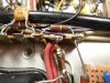
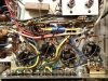
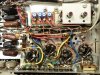
BELOW: The right channel tone control circuits, crowded to be sure. The white electrolytic caps can virtually always be considered as bad, as they were in this case. You really can't see it in this pic, but the tubular .002 uF cap at the bottom of the chassis that is under the left tone control was leaking notably due to over voltage at turn on. The brown/dark brown coupling caps of the type used in this unit in my experience rarely leak, but often go intermittent, so they get replaced as well.
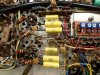
BELOW: The right channel tone control circuits recapped. The old selenium rectifier has now be changed out with silicon as well.
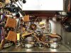
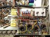
BELOW: The left channel tone control circuits recapped, along with the cleaned up balance control wiring. Once the new power switch arrives the volume control can be reinstalled to complete the area. The clip leads lead to an external monitor amp so I can test out the tuner and preamp sections, while the power amplifier section tubes are completely removed from the set. The wiring from the loudness switch has also been replaced awaiting re-installation of the volume control. It has been extended so as to eliminate any potential threat of breakage from physical movement of the volume control, even though the volume control assembly will be more tightly secured before re-installation.
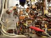
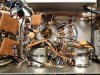
BELOW: The recapped tuner sections.
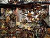
BELOW: The recapped loudness switch with repaired wiring.
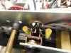
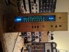
BELOW: For Rob, to help get the ugly image of the blue LEDs out of his head. Note how much brighter the new FM eye tube is on the left side of the set as compared to the existing AM eye tube. The original FM eye tube was much dimmer than the AM tube is now, almost unusable due to being so dim. There is no real reason to have both tuners operating at the same time anymore, so its no real issue, but does show the use level of the AM tube over a new FM eye tube. The set is shown receiving an average strength Atlanta FM station, and a Nashville AM station while I was playing with the AM eye tube closure levels.
In any event, with this particular unit, removing the volume control and recapping all of the mylar and small electrolytic caps throughout that level provided not only an opportunity to clean up a previous tech's work around the volume/balance control area, but also some of Fisher's as well! The smaller physical size of today's components helps to clean things up as well. When the new power switch arrives, then the volume control can be reinstalled to complete the work of the original circuits on that deck. The only other work on this deck will be the addition of individual bias/balance controls and potentially some of the EFB circuits as well -- this where the old DC Heater/bias supply's filter can cap once resided.
In yesterday's mail was the CE Distribution order for all the power supply caps, so that timing was perfect. Work on the upper deck (based on an inverted position) can now get started next week. The tubes were mailed out on Friday, so they should be arriving the first of the week, along with the power switch as well. So things are coming together.
A couple of points of note to pass along:
1. The TA-800 uses (in part) .002 uF coupling caps from the final tone stage to the volume control. So does the TA-600. In both units, these caps are rated at 250 vdc. In the 600, because of the slow warming rectifier tubes this is no problem. In the 800 however, the SS power supply produces a start up voltage well in excess of the voltage these caps are rated for. In Rob's unit, one was leaking so bad as to place well over 100 vdc across the balance/volume control combination. With no other intervening coupling caps, advancing the volume control then places a positive high voltage on the control grid of the 7199 driver tube. This not only caused the one channel to be dead (the tube saturated) but also is very likely one of the reasons these tubes tested so poorly in his unit. The other cap was leaking significantly as well, although not nearly to the extent that the one noted above was. Therefore, in at least the TA-800, the voltage of these caps (C114/C116) needs to be raised accordingly. Because of the time constants involved, a 400 volt rating is quite adequate, but 250 volts is regularly exceeded at start up.
2. For all the discussion of what caps should and don't need to be replaced by type, the cathode bypass caps in the tone/line stages (C86, 87,118, 119) were all completely open in this unit. The ceramic looking small electrolytic caps used at this point in time at Fisher for this service have not shown to hold up well. They are not particularly easy to get to, but absolutely need to be replaced with any rebuild of these units.
3. One of the things I've noted with in 800C/1800 design is the poor relative calibration of the signal strength meter when set for the AM band, versus that for the FM band. The TA-800 appears to be much in the same keeping of this observation, if not starting it: the AM section just produces notably less eye tube closure on a strong signal than the FM section does. To be fair, the AM section in this unit has two dead tubes, so I'll know more when the new tubes arrive -- but that's my initial observation anyway. This is not a circuit defect, but a design one. I have a sneaking suspicion that the reason for this has much to do with the same reasons I've stated for Fisher's as designed unusually high threshold for their MPX Stereo receivers to either trigger the Stereo Beacon lamp or produce a steady eye tube in stereo mode with the 400 receiver: noise, and specifically, AM noise. It is the same AM static heard in weak FM MPX stereo broadcasts that you hear in traditional AM broadcasts as well. Therefore, by making only exceptionally strong AM broadcasts produce the same relative eye closure as that of typical FM broadcasts, it will be understood that anything less is an invitation to noise in the reproduced sound. Today however, such calibration is a moot point, with a more practical calibration offering a more usable indication, just as lowering the MPX trigger threshold does. I've already issued a modification for how to address this in the 800C/1800 receivers, but I'll first see how this one does with the new tubes, and then assess from there.
Dave
A few pics to show where things currently are:
BELOW: The right channel tone control circuits, crowded to be sure. The white electrolytic caps can virtually always be considered as bad, as they were in this case. You really can't see it in this pic, but the tubular .002 uF cap at the bottom of the chassis that is under the left tone control was leaking notably due to over voltage at turn on. The brown/dark brown coupling caps of the type used in this unit in my experience rarely leak, but often go intermittent, so they get replaced as well.
BELOW: The right channel tone control circuits recapped. The old selenium rectifier has now be changed out with silicon as well.
BELOW: The left channel tone control circuits recapped, along with the cleaned up balance control wiring. Once the new power switch arrives the volume control can be reinstalled to complete the area. The clip leads lead to an external monitor amp so I can test out the tuner and preamp sections, while the power amplifier section tubes are completely removed from the set. The wiring from the loudness switch has also been replaced awaiting re-installation of the volume control. It has been extended so as to eliminate any potential threat of breakage from physical movement of the volume control, even though the volume control assembly will be more tightly secured before re-installation.
BELOW: The recapped tuner sections.
BELOW: The recapped loudness switch with repaired wiring.
BELOW: For Rob, to help get the ugly image of the blue LEDs out of his head. Note how much brighter the new FM eye tube is on the left side of the set as compared to the existing AM eye tube. The original FM eye tube was much dimmer than the AM tube is now, almost unusable due to being so dim. There is no real reason to have both tuners operating at the same time anymore, so its no real issue, but does show the use level of the AM tube over a new FM eye tube. The set is shown receiving an average strength Atlanta FM station, and a Nashville AM station while I was playing with the AM eye tube closure levels.
Last edited:




 we can stuff in this chassis and still make it smaller!!!
 The bean counters must have loved this exercise by engineering!!!