• The move to the new server is done. There are some software and database maintenance updates in process. This has us passing the hat around to help out. We appreciate any donations. Seriously, even a dollar helps. The payment page may be found here - https://www.audiokarma.org/support.html

BA-F1 restore

I thought I should add a few comments as the owner of the BA-F1 which John has been restoring in the past couple of months.

Firstly to thank John for his excellent, thorough work. I've followed this thread with much interest since John started it, and it's been great having a grandstand view of the process. John has also been great at keeping me up to date via private messages, and giving me clear options when there was a decision to take on a particular issue.

Secondly, just a few listening impressions on the final product. Ideally I would partner this power amp with the CA-F1, but that's going to have to wait until one of those appears on eBay for sensible money. For the moment I'm using an Audiovalve Eclipse preamp. Speakers are Triangle Signature Theta (standmounts), and the source is a Leema Antila IIS CD player. For reference the other amps I've become very familiar with in recent years is a Chord CPM2650 and a Sony TA-F7 VFET (both integrated amps).

I will try to avoid the type of hyperbole that you find in hif-fi magazine reviews, but the Eclipse / BA-F1 combo sounds superb to my ears. From the top to the bottom of the frequency range it sounds completely balanced, and one thing I've particularly noticed is the way it seems to make the speakers 'disappear'. The soundstage seems to extend several feet from both sides of the Thetas, and also from top to bottom. The other aspect I've noticed is that the combo is not lacking in dynamics, and is very precise in the way instruments are placed within the music. The last observation is that it renders male and female voices superbly. Overall I have had the real sense that the band is playing live in the room in front of me.

So, I'm very impressed. I'm keeping my eyes out for an AU-X1 (an amp which doesn't ever seem to be advertised for remotely sensible money), as I'd be interested to compare it with this combination.

And thanks again to John for his very diligent work.
 
Was redirected here by John from another thread (http://audiokarma.org/forums/index....f-a-sansui-au-919.698011/page-6#post-11464626) - let me share my solution for mounting the TO-3P transistors to the original heatsink of the BA-F1.

Originally my intention was to follow the original implementation, using gold pins to connect B and E to the original socket holes. However the ones I ordered did not really live up to my expectations (flimsy and too short), and also I did not like the idea of drilling holes and soldering so close to the housing. I decided it would be best to keep the original leads, if possible. This posed 2 problems:
  1. The bending radius would have to be too small, as the leads are very close to the heat sink surface;
  2. The leads are not square, too wide and thin for the TO-3 sockets (they expect a round pin 1mm dia).
The first problem was resolved using a ceramic insulator. This added 2.5 mm distance. Added bonus is that thermal conductivity is reported to be far superior to Mica insulators :)

Problem 2 was addressed by applying some mechanical abuse; as the leads core material is copper, this should be OK. First I narrowed the leads a bit by applying pressure with a pair of flat pliers, and rounded the edges in the same way. Then I twisted the leads around their respective axes to have the widest part in connection with the metal connector in the socket hole. Cleaned with DeOxit and the contacts feel tight.

TO-3P_mod_closeup.jpg Side view of modified transistor. Top left the ceramic insulator can be seen.
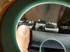
BA-F1_outputs_closeup.jpg and all 4 mounted on heat sink.

Observations:
  • The heat sink compound is much easier to apply with the ceramic insulators, as they are rigid. Still it is impossible not to get the stuff all over the place...
  • Needed longer M3 bolts for the TO-3P package (M3x20mm).
  • I added spring washers to keep a constant pressure with thermal expansion.

Not tested yet, as I am still working on the rest of the amp. And I need to decide if I will do the R channel as well.
Will keep you posted!
 
Hi all, promised to be back with an update - so here it is.
My BA-F1 has been up and running fine for a number of months now. It is in the living room driving a pair of B&W Matrix Concept 1 loudspeakers and a subwoofer. I tried both a Rotel and my CA-F1 preamp (preferred). Absolute pleasure to listen to.
Note that I have only modified one channel - the other one still has the original output power transistors. All other usual modifications (all small electrolytic capacitors, Black Flags, driver transistors, many resistors, glue removal etc.) were done to both left and right channels, so they should be identical for the rest. Guess one could call this a hybrid solution ;)
I have listened to all kinds of music, from classical via pop and jazz to funk and rock, and can not distinguish any audible differences between both channels. I have to try hard to remember which is which, actually.
So I can confirm that the mod with the TO-3P Sankens descibed above proves to work fine for me:music:!

upload_2018-10-8_17-12-4.png

Now a question. Reading the thread again, I noticed Hyperion's remark about a pair of bypass capacitors over the resistors R37,38 feeding the the driver transistors (C17/C21), see close-up from schematic diagram:

I have a question regarding C17 & C21 on the driver PCB - should they be 1000pF (Polystyrene) as per the schematic (and parts list) or 1500pF - a clumsy replacement (on the track side) by the previous owner of this BA-F1 ?

I am rounding up the very last additions to a parts order, so confirmation of this would be really helpful. ;)

Edit Update
I'm leaning seriously towards 1000pF on this one.

upload_2018-10-8_16-42-8.png

I double checked my notes and pictures of the restauration (the machine has been waiting in pieces for five years...) but am sure these were not present on my driver boards. Now my obvious concern is if it would be wise to install them as per schematics - what will be the pros and cons? An d if so, should I mount them to the underside of the PCB, or better over R37?
I am sure some of you will have an opinion!
 
but am sure these were not present on my driver boards. Now my obvious concern is if it would be wise to install them as per schematics - what will be the pros and cons? An d if so, should I mount them to the underside of the PCB, or better over R37?
If those 1000pF capacitors aren't there, I think that was a mistake by someone, and they should be installed. I assume there are positions for them on your PCB? - if so, use those positions. (You could mount them on the underside, but I recommend the topside).

Just to be clear.
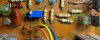
I just had a close look at your picture in the post above - and those capacitors are present on your PCB - the added 1500pF capacitors that I mentioned were in the unit I restored should not be there and were removed.
 
...
Just to be clear.
I just had a close look at your picture in the post above - and those capacitors are present on your PCB - the added 1500pF capacitors that I mentioned were in the unit I restored should not be there and were removed.
Thanks John for your quick response and your keen observation! You are absolutely correct - the capacitors are present on the PCB already. My mistake, I should have looked better; guess I was preoccupied by the picture showing some sort of polyester capacitor, where these are polystyrene foil I think?
upload_2018-10-8_20-21-4.png
F-2965/2966
Anyway, very happy with your reply.
While we are at it: it appears R37 was replaced; R38 looks original (green arrows) - this channel showed quite a few old repairs. Are these prone to failure that you know?
Following suggestions in other threads, I will replace the NFB resistors by high quality/low thermal drift metal films next upgrade pass. Thinking about upgrading all resistors in the signal path as well.
Any other candidates for upgrades suggested?
 
Are these prone to failure that you know?
Not particularly, but one channel of the one I did was a bit of a 'dogs breakfast' of repairs - so I simply mirrored the resistor changes in the previously blown channel to match the good channel. The replacement resistors fitted to the damaged channel were too big, different types, and were badly fitted so I got rid of them.
 
Thanks John for your quick response and your keen observation! You are absolutely correct - the capacitors are present on the PCB already. My mistake, I should have looked better; guess I was preoccupied by the picture showing some sort of polyester capacitor, where these are polystyrene foil I think?
View attachment 1300252
F-2965/2966
Anyway, very happy with your reply.
While we are at it: it appears R37 was replaced; R38 looks original (green arrows) - this channel showed quite a few old repairs. Are these prone to failure that you know?
Following suggestions in other threads, I will replace the NFB resistors by high quality/low thermal drift metal films next upgrade pass. Thinking about upgrading all resistors in the signal path as well.
Any other candidates for upgrades suggested?

The circled caps are styrene, they are very stable and low noise.
 
Good that this popped up @Hyperion as i have one of these coming in, and I think it has some blown OP transistors, I liked your solution there so I think this will be a handy thread!!
 
This thread is awesome, thank you to all who contribute to this. I am very lucky to own a CA-F1 and BA-F1 combo and they are quite the kit. While in excellent shape, the CA-F1 has some distortion in the mids and highs, so it’s shelved for now until I can get some time, and the BA-F1 has some crackling in the right channel for about a minute on warm up, but plays nicely. I also own a 717 and am a huge fan of Sansui, so thanks again for sharing all this knowledge!
 
Hyperion , did you compare your grand aud11ii with the BaF1. Which one is superior in SQ , build , repair ease and value.
Emphasis on SQ plz.
U already mentioned that Aux1 is a more clearer lad.
But what about some of the brothers of aux 1. Like aux 11 , aux111 and aux1111.
Im interested as i own a aux111MV(dead so far) , but a working au777D, aud707x, and getting a BA F1
 
Which one is superior in SQ,
Hard to say - depends on pre-amp used for the BA.
BA is better.
repair ease
BA is easier.
and value.
I think people will always consider the BA to be higher in value. The AU-D11 II gets a lot of flak for its build quality, and its SQ seems to get disregarded, and then there is the different electronic design which can be a problem for some.
Emphasis on SQ plz.
I can't remember any specific differences, sorry.

Apparently I said this:-
Well, bench testing complete, listening to it now for the first time, being driven by my C-2102 pre-amp (- fully reconditioned) - it's beautiful, plenty of bass with a very nicely presented image. Female vocals are very nice, and rock music makes you feel like turning it up!
 
Last edited:
This thread is awesome, thank you to all who contribute to this. I am very lucky to own a CA-F1 and BA-F1 combo and they are quite the kit. While in excellent shape, the CA-F1 has some distortion in the mids and highs, so it’s shelved for now until I can get some time, and the BA-F1 has some crackling in the right channel for about a minute on warm up, but plays nicely. I also own a 717 and am a huge fan of Sansui, so thanks again for sharing all this knowledge!

Always interesting to read about the BA-F1 and CA-F1. I have both, fully restored by John Wargo. I also have an AU-717 restored by Ed Swetich, who prompted me to find a BA-F1 and CA-F1 when he opined in an email that they were the best amp/preamp Sansui ever built. I have tried the CA-F1 but continue to use the AU-717 as preamp to the BA-F1, and driving the passive sub in my setup. For one thing, I prefer the big, stepped volume knob. And by the way, I regularly set that knob in between the steps when I am finding the right volume.
 
I have a mint AU707 (at least externally), stepped volume is the best feeling about that amp. I will definitely use it with the BAF1 too. You startled me when you said that CAF1 is laying aside and 717 is in use as a preamp with BAF1.wow.
One thing I noticed is that all these vintage amps sound thick unless their power caps are changed for fresher ones. But good caps are expensive and keep us from doing that most of the times.
 
Last edited:
I have been entrusted with a really nice BA-F1 to restore for an AK member, I collected it last night. It is in at least a 9/10 condition overall, and appears un-molested inside apart from a replacement set of OnSemi output transistors for one channel. He is not expecting it to be finished until early next year - so I have plenty of time to make a really good job of the restore.

The restore
I'll probably post some before and after PCB pictures if there is interest, as this model doesn't seem that well documented / illustrated here on AK.

Any tips?
For those of you that have already tackled one of these I would be very interested in any tips you may have picked up regarding this model. I am also interested to know if anyone knows the whereabouts of a guaranteed one channel set of OP transistors going spare anywhere, the originals in the other channel are NMC1012 // NMA1012. (The OnSemi replacements used are MJ15024 // MJ15025 which are fine really - but maybe originals are better).

Pre-amp?
The owner really wants to get a pre-amp for it, I have suggested he does everything he can to get the CA-F1 - the perfect pairing. ;)


I received my BAF1 a week ago. It a great sounding amp. The very first few minutes and i was loving it. The bass is a delight . So neat n tight and the detail is astonishing . I sat there till i was dozing , but was not leaving the seat as this was so much fun.

As i opened up the amp on weekend morning, i knew it had one channel replacements. These were 15024 and 15025.

As i went through your thread and discussions about high speed OPs, i realised that this 15024-25 are much slower (4MHz), and may someday fail suddenly leaving me dismayed .
A fellow here at AK mentioned that higher speed transistors can also fail .
And that theres some compensatory circuitry within the amp that can work for a while but both fast and slow transistors donot last long.
So my question is :
Should i also go about searching for replacements . Or just forget it as the 15025 can take that punishment, even with 6ohm speakers and prolonged play.
 
MJ15024/25 probably won't be any less reliable. TIM distortion will be measurably higher, though doubtfully audibly so, with them rather than the originals. If I had done the repair, I think I would have modified the heatsinks and used some SanKen MT200 package devices rather than dog slow MJ 15024/25. At the very least, I would have used MJ21193/94, which are, near as I can tell, copies of 2SD555/B600. Still quite a bit slower than NMC1012/A1012.
IOW, if it isn't broken, don't fix it.
 
Back
Top Bottom