• Please note that Audiokarma will be offline briefly for updates early on Monday morning, September 28th.

Barrakkuda's SX-1250 Restoration Project

barrakkuda

New Member
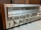
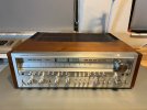
Greetings everyone. I'm starting a restoration project of my Pioneer SX-1250. I have some experience restoring retro computers and video game consoles but not vintage audio equipment, so I thought I document my journey here in hopes of getting advice from this great AK community. I'm pretty confident that I can accomplish this task and exited to get started after so long. I've spent several days reading through lots of posts here on AK about restoring this particular unit, not all though, there are around 20 pages when searching for "SX-1250", but I've found very useful information so far.

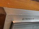
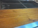
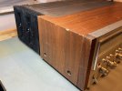
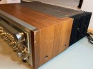
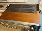
I got this unit like 5 years ago from a guy that posted it on Craigslist for $900, here in South Florida. It's a little rough both cosmetically and electrically. The faceplate has some nicks and scratches, as well as the wooden cover. I'll be taking care of those issues too. The unit turns on and it has audio in both channels but the right channel is low and sometimes has loud popping sounds. It also goes in and out of protection mode after a few minutes. I've downloaded the service manual and gotten myself a restoration and light kit from peace.love.and.music.

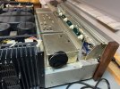
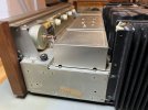
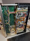
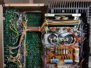
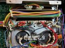
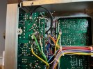
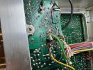
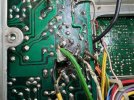
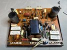
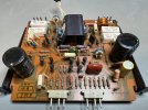
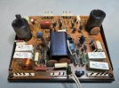
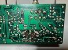
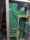
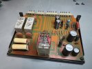
After opening up the unit to make an initial inspection I found that the Flat Amp board has suffered serious damage after previous repair attempts. Lots of broken traces in an around the area of Q8 and Q7. I'll be tackling this issue first and test what difference it makes. I'm not sure if I'll repair this board or try to get a replacement.

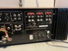
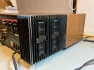
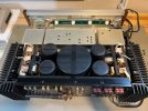
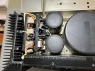
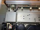
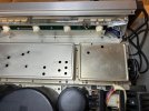
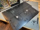
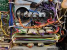
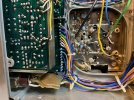
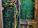
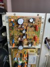
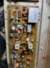
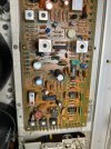
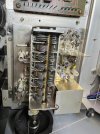
Have a look at the pictures I've taken so far. Feel free to comment, and advice/criticism is welcome.
IMG_2506.jpegIMG_2508.jpegIMG_2510.jpegIMG_2511.jpegIMG_2512.jpegIMG_2513.jpegIMG_2514.jpegIMG_2515.jpegIMG_2516.jpegIMG_2517.jpeg
 
Last edited:
Register to hide this ad
Definitely that board is butchered. I would do a full restoration including your very leaking filter caps. Extensive Parts list is on this site, search Pioneer SX-1250 restoration.
 
Definitely that board is butchered. I would do a full restoration including your very leaking filter caps. Extensive Parts list is on this site, search Pioneer SX-1250 restoration.
Agreed. Work slowly with this one please, chances are there is more poor workmanship involved with this unit. Check carefully for incorrect substitute parts too. All in all still got a bargin price IMO. Good luck! :lurk:
 
Wow, she is a survivor though.

Going to be following along as I will be tearing into mine this winter.
 
Great set of pics, thanks. Whatever it takes, doing a restore on a 1250 is worth every bit of effort and cost. There is nothing like it in the modern electronic world and never will be. I always sort of sigh whenever I look at one. Good luck on your huge project. BTW, I see a peek of what looks like an Amiga in the background, interesting.
 
Wow, she is a survivor though.

Going to be following along as I will be tearing into mine this winter.
Same here, just need to make my Mouser cap order and i'm off to the races. Bought my unit fully operational & never opened up back in 2010. Took it out of rotation 4 yrs. ago though. I started to think lady luck was going to morph into the fat lady singing, i want my original output TR's to be here another 30 yrs. so the restore begins.
 
Got mine working enough to know everything is good, just old origianl etc. The OP's is very similar cosmetically to mine.
Barrakuda, She will be the more fun homlier sister.
 
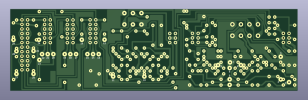
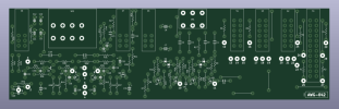
Here's what I've been up to. I've recreated the Flat Amp Board PCB (AWG-042) using KiCad software. I've replicated the original design with the same track shapes and symbols, but I've added component numbers. I'm planning to get some of these made through an online prototyping service. Hopefully they work the first time! This is my first attempt at creating a PCB, so any feedback is appreciated.

As a backup plan, I also got my hands on a replacement AWG-042 assembly from eBay, just in case I decide not to go ahead with the new PCB.

Here's the new PCB. Before I send it out and attempt to use it with my SX-1250, I'll need to thoroughly triple-check everything.
Screenshot 2023-10-19 at 1.12.13 AM.pngScreenshot 2023-10-19 at 1.12.21 AM.png

The replacement. Not in the best shape but much better than what I've got.
s-l1600 (1).jpgs-l1600.jpg
 
Looks like the unregulated power supply caps have been venting.
 
Today, I received the new AWG-042 Flat Amp board PCB, which I had manufactured through PCBWay. In my opinion, it looks good. The minimum order quantity was 5 boards, so I'll have 4 extras available for anyone who might need one. I'll list them on eBay. I've thoroughly inspected this new board and everything appears to be good.

Initially, I was a bit undecided about using it to repair this receiver because I was able to obtain the original replacement board. However, the replacement also has some minor damaged traces. Consequently, I've decided to proceed with using the new one.

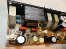
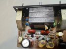
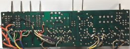
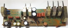
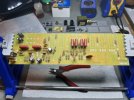
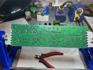
Old vs New Flat Amp Board AWG-042 - Side 1
IMG_2709.jpeg

Old vs New Flat Amp Board AWG-042 - Side 2
IMG_2708.jpeg

I've already gone through most of the components on the board. I've cleaned the switches and pots and checked all the resistors, diodes, and capacitors that won't be replaced.

One thing that concerns me is the volume control pod (ACV-169). After cleaning and testing it, I've noticed some unusual readings that concern me. I'd appreciate anyone's assistance in confirming this issue. Below are the readings I'm getting from the pot when cycling through each step from left to right. I was expecting the resistance to increase linearly, but instead, it fluctuates up and down at different points. Another thing about it is that when I shake it I hear and feel something loose and rattling inside. I slit open the label on the back side and saw that this pot is the type that doesn't have the pressure clip, so it's not easy to fully disassemble. Most likely this one's bad? When I tested the receiver I was able to raise and lower the volume, but had issues with the right channel popping, crackling and sometimes going out.

Position: Channel 1 / 2 resistance
1: 0.4 / 0.4
2: 43.0 / 54.6
3: 174.6 / 171.4
4: 100.3 / 103.2
5: 250.0 / 237.1
6: 252.4 / 251.3
7: 1366 / 1246
8: 627 / 641
9: 1793 / 1605
10: 1275 / 1303
11: 2605 / 2365
12: 2604 / 2632
13: 7740 / 7670
15: 5171 / 5199
16: 10220 / 9870
17: 6800 / 6870
18: 11820 / 11870
19: 8760 / 8820
20: 14080 / 14090
21: 11950 / 12040
22: 17610 / 17650
23: 17000 / 17140
24: 22850 / 22640
25: 20610 / 20730
26: 26650 / 26560
27: 24820 / 25000
28: 30850 / 31240
29: 29940 / 30070
30: 36210 / 36220
31: 35670 / 35830
32: 42260 / 42250
33: 41820 / 41970
 
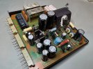
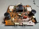
Here's the new board, almost fully populated with components from the flat amp board restore kit, along with any items that are not being replaced. There's something worth noting about the two FETs on Q5/Q6: the service manual specifies 2SK30, but I found 2SK34's on the original (damaged) board. The replacement flat amp board I purchased from eBay came with the correct two 2SK30 FETs, so I installed those on the new board.

Another observation I made on the original board was that one of the electrolytic capacitors (C22) had been incorrectly installed in reverse polarity. The only thing that's currently missing is the volume control pot (ACV-169). I've found a replacement on eBay, so I'll wait for it to arrive before testing and comparing resistances between it and the one I already have.

Some pics:
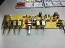
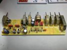
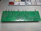
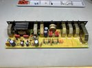
IMG_2714.jpegIMG_2715.jpegIMG_2717.jpegIMG_2716.jpeg
I'll give it a good clean after I install the volume control.
IMG_2718.jpeg
 
Today I received the replacement volume control and it tested good so I soldered it to the flat amp board and put the board back in the receiver. The good news is that the receiver still works, bad news is that issue with the right channel is still there. I tested with and without the DBT and the receiver didn't go into protection mode, as it was doing before, but I'll have to leave it on for longer to make sure. For now I'll continue doing the rest of the boards and test the receiver after each one. There are some wires I need to replace that go from the Flat Amp Board to various places but I need to order the proper wires. I might open up the bad volume control to see if it can be fixed.

Here are some pics:
New board fully populated.
IMG_2724.jpeg

The new board installed on the receiver. I'll fix those wires soon.
IMG_2727.jpeg
 
Great set of pics, thanks. Whatever it takes, doing a restore on a 1250 is worth every bit of effort and cost. There is nothing like it in the modern electronic world and never will be. I always sort of sigh whenever I look at one. Good luck on your huge project. BTW, I see a peek of what looks like an Amiga in the background, interesting.
That keyboard looking thing in a couple of the pictures is a Commodore 64, from my small collection of retro computers and gaming consoles.
 
Back
Top Bottom