• The move to the new server is done. There are some software and database maintenance updates in process. This has us passing the hat around to help out. We appreciate any donations. Seriously, even a dollar helps. The payment page may be found here - https://www.audiokarma.org/support.html

...Before I start smashing these with a hammer!

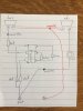
Please somebody help out a noob. I'm trying to re-install the drivers in my KLH model 6. I don't understand the wiring diagram!

Disclaimer: These are NOT the model 17, 20, 23, etc etc. These are the late* model 6. please don't post photos of the sloppy messes inside of those 17s (that I've already seen, believe me).

Please watch the 3 minute video to get the full picture. This is frustrating and i would love to get these up and running again, without blowing my beautiful NAD amp. Thank you, sincerely.

 
Last edited:
Register to hide this ad
Ok, I just removed the red and black coming from the coil on the back of the cabinet from the equation, and everything seems fine.

So, what is the purpose of that coil, and how is ACTUALLY supposed to be wired? Thanks
 

Thank you, but I've seen that a hundred times. It doesn't explain the 4 ground wife's I have in my speaker. Please see the video. Thanks for helping.

The coil is probably the 0.4 Henry inductor and should be connected to the low frequency driver (woofer).

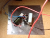
Ok, so if you watch the video, I attach the ground from the 0.4 henry inductor to the woofer. I also attach the ground from the terminal to the woofer (or there is no sound) the ground from the tweeter must also be attached to the terminal ground.. So, there are supposed to be 4 black wires capped together?? When I do this, the speaker can't handle any load and crackles very badly.

For now, they are running perfectly with the he runs inductor not connected at all.

I need help, but the easiest way to answer is if someone looks at the video and tells me what to connect where. It is a crystal clear shot.
 
Thank you, but I've seen that a hundred times. It doesn't explain the 4 ground wife's I have in my speaker. Please see the video. Thanks for helping.

It does, but you have to consider the schematic isn't a wiring diagram.

The black wire from terminal A is easy, that goes to the negative of the woofer and to the negative of the tweeter.

Remove the wire nut on the red wires and separate those three. Now, reconnect only the red wire from the coil to the B terminal.

Next, connect the black wire of the coil to the red wire going to the woofer.

Now, connect a jumper between the B and C terminals to run the system full range. Check the woofer polarity by momentarily connecting a small battery AA, C, D, etc. with the negative terminal to the A connection and the positive terminal to the B/C terminal. Note which way the woofer moves. If it moves out you are good to go. If it sucks in, swap the two wires on the woofer terminals and check it again.
 
Last edited:
Black wire from the coil is not a ground. By connecting it the way you did, you put the coil across the speaker terminals. The amp was therefore driving the coil and wasn't very happy about it.

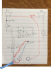
Comparing your wiring to the schematic, here's how to fix it.

First take care of the tweeter. Connect together - the ground from the tweeter "swingin' in the wind" AND the ground wire coming from the woofer, AND the ground coming from the post.

Second take care of the woofer. You have THREE red wires connected with a marette. Remove the red wire going to the woofer from this connection and connect it to the black wire from the coil instead.


IMG_6680.jpg
 
Last edited:
Black wire from the coil is not a ground. By connecting it the way you did, you put the coil across the speaker terminals. The amp was therefore driving the coil and wasn't very happy about it.

Comparing your wiring to the schematic, here's how to fix it.

First take care of the tweeter. Connect together - the ground from the tweeter "swingin' in the wind" AND the ground wire coming from the woofer, AND the ground coming from the post.

Second take care of the woofer. You have THREE red wires connected with marette. Remove the red wire going to the woofer from this connection and connect it to the black wire from the coil instead.

Yup, pretty much what I just said but perhaps a bit easier to follow. :thumbsup:
 
I was probably editing or something when you posted. No biggie, either way the OPs speakers and amp will like the changes.
 
Thank you.
Black wire from the coil is not a ground. By connecting it the way you did, you put the coil across the speaker terminals. The amp was therefore driving the coil and wasn't very happy about it.

Comparing your wiring to the schematic, here's how to fix it.

First take care of the tweeter. Connect together - the ground from the tweeter "swingin' in the wind" AND the ground wire coming from the woofer, AND the ground coming from the post.

Second take care of the woofer. You have THREE red wires connected with a marette. Remove the red wire going to the woofer from this connection and connect it to the black wire from the coil instead.


View attachment 976947
Dude for that drawing, and the "swinging in the wind" knock, I owe you big time. This is all I needed. If the diagram from klh is 'not a wiring diagram' then it's useless.. Which it was because that coil throws a huge wrench into the works.

I would never have thought to connect the black wire from that to the post. OK.. Now to go rip these things back open.
 
Now, connect a jumper between the B and C terminals to run the system full range. Check the woofer polarity by momentarily connecting a small battery AA, C, D, etc. with the negative terminal to the A connection and the positive terminal to the B/C terminal. Note which way the woofer moves. If it moves out you are good to go. If it sucks in, swap the two wires on the woofer terminals and check it again.

I'll see when I get it open, but shouldn't that jumper already be in place? I'm not building the crossover from scratch, it should've been wired that way to begin with no? Any wire from a to b will work?
 
Thank you.

Dude for that drawing, and the "swinging in the wind" knock, I owe you big time. This is all I needed. If the diagram from klh is 'not a wiring diagram' then it's useless.. Which it was because that coil throws a huge wrench into the works.


A schematic shows the electrical path, it isn't inherently intended to show the physical assembly/layout/arrangement. There are any number of ways the parts can be laid out, but there is generally only one way they properly connect and that's the point of a schematic.

You can see the electrical path from the B terminal, though the coil, to one terminal of the speaker.
 
I'll see when I get it open, but shouldn't that jumper already be in place? I'm not building the crossover from scratch, it should've been wired that way to begin with no? Any wire from a to b will work?

The B to C jumper to which I refer should be on the terminals on the outside. Normally it would be there but I have no way to predict if it actually is because it could have been removed.
 
@Sonofnothing

Haven't penciled out the switch, but the terminal connections need an update on the drawing - presuming the terminal plate is original/as the schematic shows it should be. See below.

The coil supplying the woofer should be connected separately to the "B" terminal, not combined with the tweeter circuit at the "C" terminal. It's the external jumper I mentioned previously that joins them for normal/full range operation or when removed allows biamping/biwiring.

Then A is where you hook the amp (-) and the amp (+) goes to the B+C jumpered connection.

You did check to be sure the woofer moved "out" when a small battery connected with (+) to B and (-) to A, yes? Be sure it's the same on both speakers.

Picture1.png
 
Last edited:
No jumper is necessary. As seen in the video, there are only two posts ( +ve and -ve) on the back of the speaker. (i.e., B and C on the schematic are already connected internally)

KLH Model 6-2.jpg
Screen Shot 2017-07-31 at 8.43.42 PM.png
 
Last edited:
No jumper is necessary.

Interesting.

m6.png

And this.

4110246491_57a237f997.jpg


Must be earlier/later versions?

Regardless, if the OPs don't have the A, B, and C terminals then for sure none of the stuff about that is pertinent and should follow your diagram for the wiring. Probably explains a bit too why the schematic was giving a fit to the OP.
 
Last edited:
Enjoyed your narrative in your video! whoaru99 and willyover are spot on. While your inside you should replace those dreaded 40 year old black/red caps from Mexico!
 
The crossover network in your KLH 6's and in other Kloss speakers (like the Advents) is drek. There are threads about on the WWW that entertain new ideas about these networks, where components and switches are either changed or bypassed. If you want them to remain as original, have at it but there are better solutions out there. When I had a pair of OLA's, I was thinking of a network substitution. That would leave the original intact for later resale and still offer up a better voiced network.
 
Interesting.
Must be earlier/later versions?

Yes, I have the late version, the woofers and crossovers are not epoxied into the cabinet. Thanks so so so much for the diagram you drew out. I still don't understand it, but I am able to follow along and made it happen. The black coil to the positive woofer? I would never have attached red and black. But, ok!


Enjoyed your narrative in your video! whoaru99 and willyover are spot on. While your inside you should replace those dreaded 40 year old black/red caps from Mexico!

Yeah, I did buy the new caps.. I entered the part numbers found on this forum. The caps look WAY too small compared to those dreaded Mexican caps. I don't want to blow things up. Also my soldering skills are shite. Maybe I need different solder, because I tried tinning wires, and it was a joke.
 
Back
Top Bottom