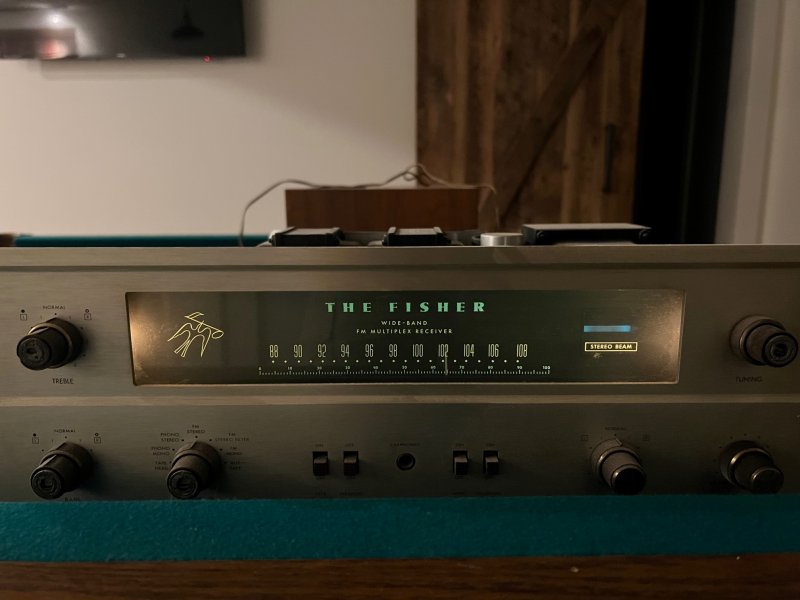
• The move to the new server is done. There are some software and database maintenance updates in process. This has us passing the hat around to help out. We appreciate any donations. Seriously, even a dollar helps. The payment page may be found here - https://www.audiokarma.org/support.html

Beginning my 400 Restoration

moodyj2000

Member
I am a tool guy and I like to tinker. Not an expert but willing to learn. Recently picked up a Tenma 72-455a Signal Generator, Tektronix 2205 Oscilliscope, Tripp Lite Isolation transformer, Staco Variac and a couple of 8 Ohm 100 watt dummy loads from Parts Express. I had already built a DBT and own several DMM and a digital single channel Oscilliscope. Not all of this is for the 400. I have accumulated a lot of gear that needs help so its money not waisted as long as I put the time into learnign to use it right.

So now I have enough tools to be dangerous. Plugged my 400 into the DBT without the power tubes in place and the 150 watt bult glowed brightly and then dimmed down to a faint glow. At least that part looks right. Now I need to dig further.

Any recommendations on what to test next? I have ordered a new safety cap for the unit and will replace that when it comes in. I was thinking about putting the power tubes in and hooking up the dummy loads and signal generator and seeing where I am at but wasn't sure if that would be a prudent next step.
 
Register to hide this ad
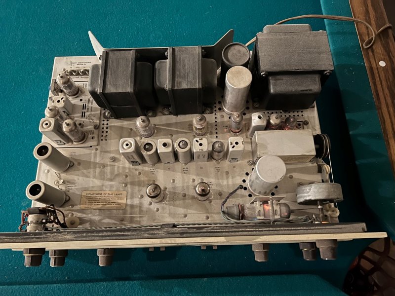
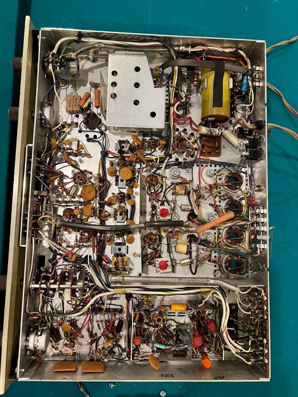
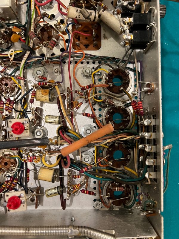
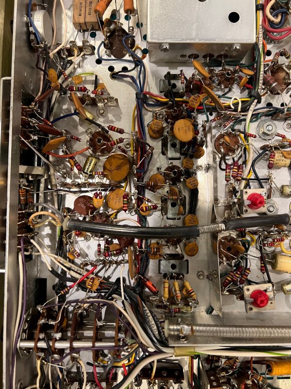
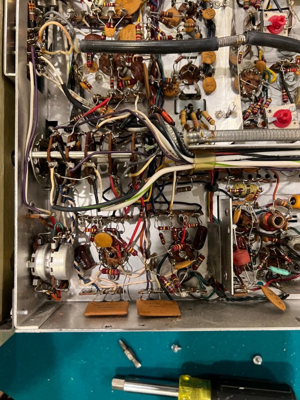
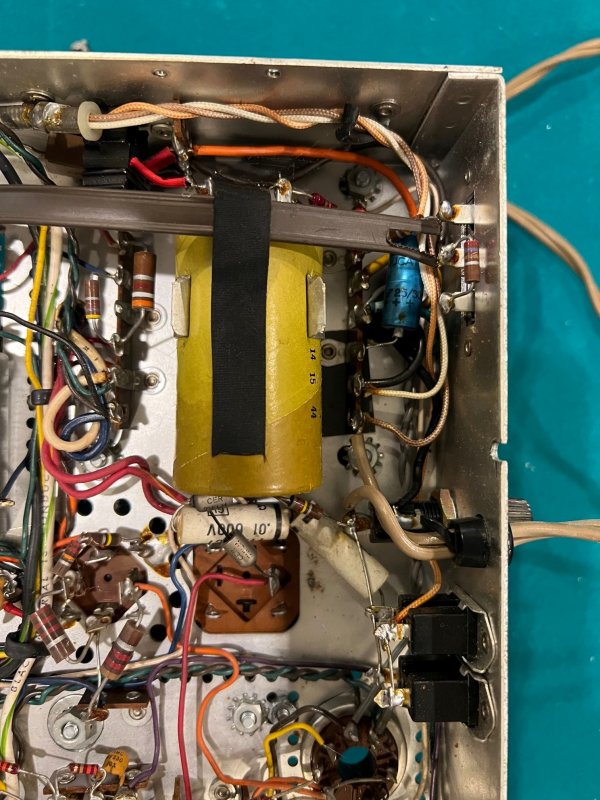
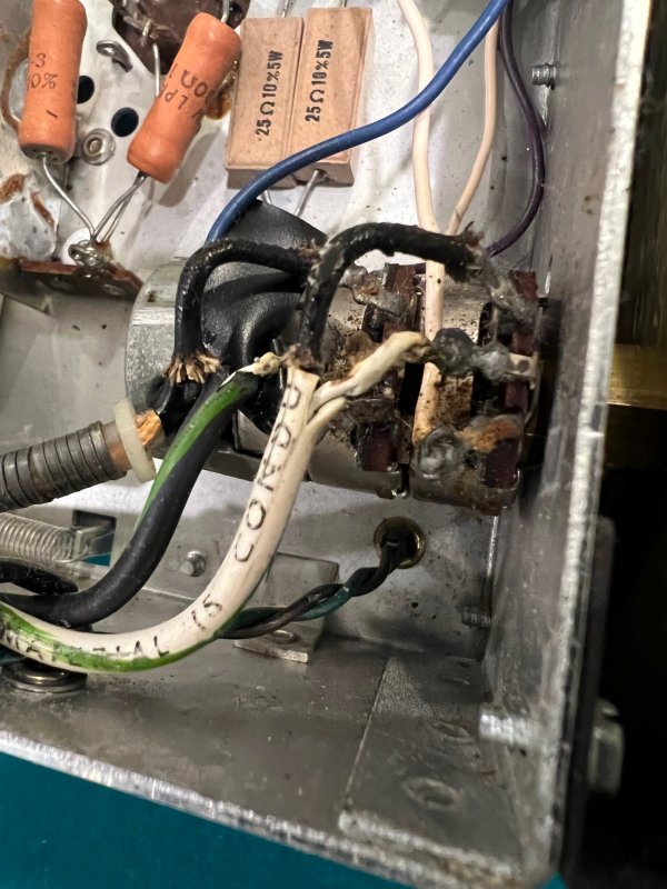
Some more pictures of the unit.
+
 
Other than that nasty power switch the 400 looks nice and clean. I restored one some time ago and it is a nice sounding receiver. Lots of good threads on restoring the unit here, there are certain recommended items and a lot of potential enhancements. Filter re-cap and bias supply rebuild are high on the list, then coupling capacitor replacements and screen stability resistors and and...:):):)
 
Very possible that someone sprayed flammable contact cleaner into that switch which is a no no. The power switches are know to go bad, we install inrush limiters to help extend their life.
 
.... Plugged my 400 into the DBT without the power tubes in place and the 150 watt bult glowed brightly and then dimmed down to a faint glow. At least that part looks right. Now I need to dig further.

Curious: When you tested on the DBT, did you apply power to the unit via the 400's switch or via an external switch? That would immediately tell you if the switch on the 400 is good. Also, via the pics you've posted, there's no way to tell if there is arching damage to the switch. Oftentimes, the entire assembly is referred to as the "switch." Actually, the switch is the section at the very back of the component, the sections closest to the face plate being the stereo pot. Your pics show a really, really dirty pot which would affect proper tracking at best, or volume drop outs at worst. And the only way to determine the health of the pot is to use it.

I think it's obvious that someone has already messed with the pot for whatever reason. I'd leave it as an item high on the punch list once the other aspects of the restoration have been completed. Tearing it down for a thorough inspection and cleaning is work but fun for a committed tinkerer.
 
I tested it using the 400's switch. Really makes me nervous as there is significant signs of arcing and the wires are in bad shape. There has been some electrical tape wrapped around the wires to cover open areas. Whatever happened was energetic so I definitely have this high on my resolution list. A quick look at ebay returns no direct equivalents. There is a R50160-92 from a fisher KX-200. It is dual, 500k but a different model number. The 400 uses a R50160-104. Any idea if the latter would work?
 
OK, now we know that the SWITCH part of the assembly works you have to determine the health of the POT. Unless someone took a flamethrower to it, or fell asleep while soldering, there would be no reason to have any arching in the POT. And frankly, there is no way for an arching event to take place in the POT sections. Even if there was a fire in the switch, it is highly unlikely that it would migrate to the pots. I think what you have is burnt flux from a prior effort to either repair or replace the assembly. I'd hold off changing it until you can determine whether the pot itself is not functioning to your satisfaction. Whether you keep the existing pot, or replace it, you're gonna have to deal with the state of the wiring as you now have it. That's why I suggest holding off until you can thoroughly assess the condition of the entire shebang. No sense chasing something that you might not need. Also, finding a replacement pot is a real adventure, both in the quality of the replacement, and its cost. I'd hold off.

If you're intent on picking up a replacement Fisher pot, then I'm pretty sure the KX version will work so long as it is a 500k pot. I don't know if a KX has a loudness function but if it does, then I think you're set with it.

One last thing: I'd avoid using the 400's switch for now. Once you have a thermistor added, the ramp up is slow so you'll have to worry les about arching damage. Use the switch on the DBT, or other means to apply power. In all my units, even with thermistors and new switches, I power on with the switch on my bucking transformer. More paranoia than necessity but hey..... :
 
You bring up a few topics I have meant to ask about. The thermistor add and running the 400 on full line voltage vs a bucking transformer. Any details on either of those? I have read some about the differences between the old voltage available and current voltage.
 
We have to separate two overlapping issues: switch preservation and unit design. Re the switch, the primary purpose of the thermistor is to “slowly” energize the unit so as to limit the effect of the onrush current that has fried many a switch. Mind you, the switch part of the control is fairly replaceable but why go there if it can be avoided. A secondary freebie benefit is that the thermistor drops the voltage a hint, leading to your next question.

If you look at the schematic to the receiver, you’ll see that it was designed with an applied voltage of 117vac, the voltage supplied at the time. That’s it. The parameters of the design was centered around the one constant that could be somewhat controlled. Nothing, however, would permit the factory to construct a “perfect” unit given the wide tolerances of the components used. That is why when referencing the schematic during restoration, “close enough” becomes the standard. And what does this have to do with operating voltages and bucking transformers? Well, if you look somewhere in the paperwork, or maybe on the unit itself, there will be a note that’ll give you an operating RANGE. So assuming you don’t have any components that cannot now handle today’s wall voltages, plugging straight into your wall voltage should be fine. Operating either too high or much below the design standard would affect performance. The bucking transformer just allows many of us to “optimize” use of our units in line with the designers’ intentions.
 
Last edited:
Looks like a GE Type CL thermistor CL-80 would work and give about 2 Volts of drop on a running load. I am assuming this would simply be wired in series with the switch?
 
Correct. Install it in the back between the power cord and the Fuse, so you don't have any "flying leads". The cord may tie into the terminal strip next to the fuse. Use the terminal strip and the fuse holder to tie it down.
 
I was just getting ready to ask if on the back in would work. I seem to remember a picture of one of yours that showed it but couldn't find it again. Trying to put together a parts list now. Doing this and the safety cap you mentioned in another post at the same time.
 
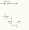
Alright electrical experts I was curious about something. What does the parallel resistor and capacitor to ground do on the input side of the power transformer? I know the cap is the safety cap but just curious about the circuit in general.
 
The cap is an AC bypass cap that provides a virtual ground for the receiver, while the resistor provides a discharge path for any static charge that might build up on the chassis during any electrical storms if the receiver is connected to an outdoor antenna. That's why the resistor is generally only used on tuners and receivers.

Dave
 
@dcgillespie I didn't know that was why thanks.

@moodyj2000 Have you hooked up a multimeter to your AC outlets? At the time of my fisher 800c rebuild I had tech do this and he lived in Texas and I in Massachusetts (long story). He asked me if I knew what my line voltage was and at the time I said I don't know because I didn't know it was something I could of used a multimeter for :rolleyes: .

Anyways he did everything that was recommended and told me he setup up my 800c at 119V... After a few output redplates I finally learned how to read/bias the output tubes (he did add the bias checkpoints) and later learned my AC voltage is on average at 125V and can get to 129 and stay there for a good 7 seconds at least so I bought a bucking transformer on epay. My point is knowing your AC voltage may help you determine values in the receiver where you might not need one if you use the correct values in your rebuild.

At the sametime I am glad he did it the way he did because the power transformer is cooler with the bucking transformer in use.
 
Dave, thanks for the reply. Makes since now.

My wall voltage at the house runs 125 VAC but can fluctuate quite a bit. Been meaning to put a data logger on it for a while.

A buck transformer would lower it but the fluctuations would still be there. Albeit less p-p
 
Putting together a parts list order for Mouser. Looking at the IBBA and wondering if the tolerance matters on the trimmers, resistors and capacitors? Also, on the capacitors, Dave's diagram shows 35V but only 10uF 450VDC are available now. The tolerance is 20% on those. Is that an issue? They are a month out on Nichicons at 63VDC and greater than that on 35VDC.
 
Back
Top Bottom