• The move to the new server is done. There are some software and database maintenance updates in process. This has us passing the hat around to help out. We appreciate any donations. Seriously, even a dollar helps. The payment page may be found here - https://www.audiokarma.org/support.html

Big DC Power supply. What does this do?

QSilver

Super Member
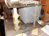
I have z bug old dc power supply from the 60s. It was originally used for running solid state systems in electro-pneumatic pipe organs and it seems quite beefy.

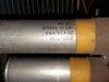
25A @ 15/13/12v

I plan on changing the capacitor bank to make sure it keeps performing well. Though there are a few parts in here that I dont understand.

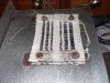
There is a wire mesh type plate mounted inside that connects between the dc output terminals. I measured 8.2ohms between the two terminals and the mesh gets warm when the psu is operating.

Can anyone tell me what it is and what it is here for? It seems to just waste power to me...
 

Attachments

  • 20160129_223720.jpg
    20160129_223720.jpg
    147 KB · Views: 125
  • 20160129_223706.jpg
    20160129_223706.jpg
    64.8 KB · Views: 120
  • 20160129_223732.jpg
    20160129_223732.jpg
    115.4 KB · Views: 118
  • 20160129_224058.jpg
    20160129_224058.jpg
    85.6 KB · Views: 113
Register to hide this ad
The power supply may be unregulated and this 8.2 Ohm resistor might keep the output Voltages from going too high with out a load on it.
You are feeling the heat of about 4.48 Watts when the power supply is running. :idea:
Mark T. :music:
 
The power supply may be unregulated and this 8.2 Ohm resistor might keep the output Voltages from going too high with out a load on it.
You are feeling the heat of about 4.48 Watts when the power supply is running. :idea:
Mark T. :music:

Thanks. I was finding it difficult to find an explaniation online. Would the presence of this resistor explain why when idling, it draws so much power? When connecting it up via a DBT, i have to put in a 200W bulb before it stops glowing on idle.
 
yeah, probably a ballast load. That would definitely make it suck power when idling. It just so happens that in front of me I'm testing my own dummy load on a similar DC supply. 8 ohms at 13 volts is better than an amp and a half.
 
Thanks for the information. Is there anything better I could replace it with? How hard would it be to turn this into a regulated power supply?
 
It depends on the amount of DC voltage available. Taking a guess at it, you can likely increase it some by changing it to silicon rectifiers. With that, you may have enough voltage overhead to build a regulator circuit. I once had a similar non-regulated supply that a friend converted for me. The core of the thing was an LM317 variable voltage regulator which basically drove a bank of TO-3 style switching transistors mounted to a heat sink. The LM317 is only good for 1 amp, but you can use it to control a larger transistor. You'd probably need 2 or more to really deal with 25 amps comfortably. I think the one I had ran 4 actually, but that was mostly because the donor heat sinks had holes for that many parts already.

http://electronics-diy.com/electronic_schematic.php?id=657

has the type of thing that my old one ran. You can just parallel more 3055 transistors to get some extra current capacity.
 
I think LM317 is about 1.5V minumum differential. That has to be covered under all operating conditions including loaded ripple.
 
Thanks - thats interesting... I hadn't through about replacing the rectifier. I tried looking it up and as far as I could see, this one is called a "Directronic Rectifier". Also, I was tihnking about needing the extra few volts above the supply... I could add another transformer inside the chasis to provide this... or if I remove the ballast resistor (if I'm thinking correctly I will no longer need) the votlage might be higher anyway?

EDIT: Just another thought - I'm right in thinking this would make it more efficient right?
 
Last edited:
I'd probably try to load it up to your expected demand then measure the AC voltage at the transformer output. I think that would be a good indicator of where you stand with regard to having enough overhead for regulation.
 
I have z bug old dc power supply from the 60s. It was originally used for running solid state systems in electro-pneumatic pipe organs and it seems quite beefy.

25A @ 15/13/12v

I plan on changing the capacitor bank to make sure it keeps performing well. Though there are a few parts in here that I dont understand.

There is a wire mesh type plate mounted inside that connects between the dc output terminals. I measured 8.2ohms between the two terminals and the mesh gets warm when the psu is operating.

Can anyone tell me what it is and what it is here for? It seems to just waste power to me...

There is no value in this thing. To make it work reliably you have to replace ALL components. I wouldn't trust 50 years old selenium rectifier. When it fries it emits very toxic fumes.
 
There is no value in this thing. To make it work reliably you have to replace ALL components. I wouldn't trust 50 years old selenium rectifier. When it fries it emits very toxic fumes.

Ok, thanks for that information - I wasn't aware of the fumes. What sort of rectifier would you suggest as a replacement?
 
35-50A bridges are not expensive. Looks like there is enough metal chassis there to serve some function as a heat sink.

Is it set up using the transformer as center-tapped FW bridge, or?
 
Big silicon bridge rectifier would do it just fine.

If the stock setup is full wave center tap, then a pair of stud-mounted rectifiers would do the job.
 
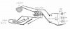
I've tried to draw the layout and connections of the power supply as best I can. I didn't draw in all the veins in the rectifier but It is roughly like I have drawn it. Although on a further look, I see that its not as simple as "every other vein" but hopefully this will help. I'm not sure if it is a half wave, full wave or center tapped supply.

Hopefully you can read my writing and make sense of the drawing.

EDIT: I've been reading up on the selenium rectifiers and it seems they make a nasty smell when they fail.... well mine was making a strange unpleasent smell when I last turned it on... maybe a warning sign?

Also, will I need a resistor to match the original voltage drop caused by the rectifier or will this benefit the idea to make it a regulated supply instead?
 

Attachments

  • Rectifier.jpg
    Rectifier.jpg
    36.5 KB · Views: 28
Last edited:
I'm thinking that is a full wave bridge. The typical full wave center tap would have one leg of the transformer as your ground and the + would come from the junction of 2 rectifier sections. It looks like your transformer does not ground, but simply feeds AC into the rectifier. Pos and neg DC come out of the other end of it.

Increasing the available voltage with a new bridge would give the regulator some overhead to work with. It needs to have at least a couple volts over your target to allow for internal voltage drop and whatnot.

I'm told that when selenium rectifiers die, it puts out something of a rancid cabbage smell. I've never had one go bad, but high current applications like this is where they tend to fail. The internal resistance increases, which causes heat, which makes it die.
 
I'm thinking that is a full wave bridge. The typical full wave center tap would have one leg of the transformer as your ground and the + would come from the junction of 2 rectifier sections. It looks like your transformer does not ground, but simply feeds AC into the rectifier. Pos and neg DC come out of the other end of it.

Increasing the available voltage with a new bridge would give the regulator some overhead to work with. It needs to have at least a couple volts over your target to allow for internal voltage drop and whatnot.

I'm told that when selenium rectifiers die, it puts out something of a rancid cabbage smell. I've never had one go bad, but high current applications like this is where they tend to fail. The internal resistance increases, which causes heat, which makes it die.

Thanks - I think I best remove that old rectifier and re build the whole thing then. Would I need a bridge rectifier? I'm looking at them now and trying to figure out what I need... I was thinking something like Repetitive Reverse Voltage 800V, Forward current 35A.... what about Forward Voltage Max?
 
Generally the mains amps off he rails rated fuses. i.e. 6amp then 6 amp. or 8 amp? load capable. rating of the mains fuses is the hint.

Sorry I don't have a link but if you post a pick if a '4 pole' tower encapsulated or is it diodes on a pcb?
 
The first question which needs answering is what you want to use this power supply for. 25 amps is a huge amount of current. 12V isn't a huge amount of voltage. Most solid-state power amps require a split rail supply of a higher voltage, so I doubt that this would be much use for a power amp.
Pre-amps don't need anything like 25 amps and having an oversized power supply offers no advantages whatsoever in my opinion (though others may disagree). In my opinion, for pre-amps it's the quality of the regulator which matters, not the raw DC. Oversized mains transformers just pollute the audio environment with stray magnetic feilds.

So what did you have in mind for this power supply?
 
The power supply was oringially designed for use in pipe organ electro-pneumatic systems - where stop, key or any other action was controlled and operated by 12-16V solonoid magnets - usually these are 50-75 Ohms IIRC. This is why the amperage is so high. These systems are still in use today and I do use this supply in my own organ system at home. I want to refurbish it to keep it running reliably and maybe make it into a regulated power supply partly as a project and partly as an upgrade.
 
Back
Top Bottom