• The move to the new server is done. There are some software and database maintenance updates in process. This has us passing the hat around to help out. We appreciate any donations. Seriously, even a dollar helps. The payment page may be found here - https://www.audiokarma.org/support.html

Big DC Power supply. What does this do?

They're useful for running mobile radio gear. I have a 40 amp 6-15vdc regulated supply that I use for CB stuff and working on car amplifiers. Short of stuff like that which actually needs a relatively constant output voltage though, there isn't a huge advantage to a regulated supply for things like solenoid valves.

If the existing selenium rectifier setup is a full wave bridge, then you'd need a full wave bridge rectifier to sub for it.
 
I would also like to use it to run things like that too Gadget, which is why I wanted to try out a regualted supply. Is the rectifier I linked to not a full wave bridge?
 
I'm curious,
(I really don't know)
I'd think a supply with a choke , multiple caps and a ballast resistor would be adequately clean to run car audo , radios.
It would seem like a relatively clean supply , not regulated but up to the task. Is there an inherent need in these applications where you need super stable dead on voltages?
I'd be curious to see the output on that under no , and load conditions.
 
You're probably right, but I thought I could try making a regulator for it just for practice. I will still need to replace the rectifier though. I could test it without and maybe with load... It works ok at the moment besides drawing a lot of power at idle. I think it's down to the resistor and maybe old caps. Regulating it would reduce its idle current consumption so that's one reason I wanted to regulate it.
 
Unless your cost of electricity is really high, you can pay for many hours of 5W dissipation with what conversion could cost. Would cost me about $3.90 per year at 24 x 365.
 
So the new bridge rectifier (if the one I linked to is ok ratings wise) will give me a slightly higher voltage anyway so I would need to push that back down at least... that's another reason why I thought of regulation.

Unless your cost of electricity is really high, you can pay for many hours of 5W dissipation with what conversion could cost. Would cost me about $3.90 per year at 24 x 365.

That's true, but as I said I wouldn't mind building a regulator as a project. But if it isn't the way to go then thats okay. I could order the rectifier and new capacitors now, but what to do about the increase in voltage after replacing the rectifier for the new silicon one?
 
I've taken some readings from the unit. I disconnected the transformer from the rectifier and measured the voltage on the windings without any load.
12V : 15.2V
13V : 17.1V
15V : 18.6V

Next, I reconnected the rectifier and took measurements again on the transformer windings, with the rectifier, capacitor bank and ballast resistor.
12V : 14.5V
13V : 15V
15V : 17V

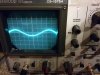
Finally I took measurements from the DC output with an oscilloscope and measured both ripple current and voltage.
12V : Ripple 200mVAC : 11.5VDC
13V : Ripple 115mVAC : 13.3VDC
15V : Ripple 125mVAC : 14.3VDC

I noticed that on the 15V settings, the waveform was twitching on the scope which the other two didn't do and just before I turned it off after doing the readings, the waveform of the ripple jumped and the DBT i had i it connected through, flashed and then went dim again.

My DBT has three bulbs in it and I had enough of a wattage that I was not restricting current for its idling and taking measurements. I used it as a precautionary measure.

When I was running the transformer without any connections it did still pull enough current to light up a 60W bulb fairly brightly... not sure if thats a bad sign as it is quite a chunky transformer....
 

Attachments

  • 15V Ripple.jpg
    15V Ripple.jpg
    72.3 KB · Views: 4
  • 13V Ripple.jpg
    13V Ripple.jpg
    86.2 KB · Views: 5
  • 12V Ripple.jpg
    12V Ripple.jpg
    91.7 KB · Views: 4
I've been able to revisit this in the weekend and I've removed the selenium rectifier. I was looking into using some voltage regulators to help regulate the voltage down from the transformer and rectifier's voltages and wondered if it was possible to run 5 LM138 regulators in parallel or if this is just asking for trouble?

Also, how thick do the internal cables need to be when they are carrying 12V 25A? The current ones are very thick and I wondered if they were really necessary and could be replaced with something a bit thinner?
 
I wonder if the o'scope indications really matter, or a cleaner ripple maybe different caps with low esr. as for reduction v reduction a 9 pin regulated on both channels? just need a power tap and what ever load and caps Just looking in my parts boards.. or basically a 3 pin regulator can work with a heat sink in the sm, too.. Don't really understand the end zone you're trying to hit. If an organ a little ripple is good. What you have off the sm is avg. enough to power what? what's the amperage?

I know... I'm asking dumb questions. But this is more interesting than watching zombie movies.
 
At 25A I'd say #10AWG minimum. (Which is pretty thick. For as short as the internal runs are and the likelihood that you'll ever run anywhere near 25A, #12 would probably be fine. (Technically it's free air so current ratings are higher for the conductors.) Are those protected by a fuse or a breaker?
 
I wonder if the o'scope indications really matter, or a cleaner ripple maybe different caps with low esr. as for reduction v reduction a 9 pin regulated on both channels? just need a power tap and what ever load and caps Just looking in my parts boards.. or basically a 3 pin regulator can work with a heat sink in the sm, too.. Don't really understand the end zone you're trying to hit. If an organ a little ripple is good. What you have off the sm is avg. enough to power what? what's the amperage?

I want to rebuild the power supply and replace the selenium rectifier with a silicon rectifier. Of course, this will mean the rectified DC voltage will increase to a much higher one that originally the device was capable of. I thought the best way to get the voltage back down to a 12/13/15VDC supply would be to then regulate the new higher rectified DC voltage down to the original voltages. It is a 25A version of the device and so I thought I would rebuild it with a regulator capable of 25A too. I had been using the supply as a large bench supply to test radios and other 12V equipment and I was also using it to power an old 14.4V cordless drill (you cant get the batteries anymore). I did have another thought - use a voltage regulator as a reference for a large transistor that can carry that amperage?

At 25A I'd say #10AWG minimum. (Which is pretty thick. For as short as the internal runs are and the likelihood that you'll ever run anywhere near 25A, #12 would probably be fine. (Technically it's free air so current ratings are higher for the conductors.) Are those protected by a fuse or a breaker?

Thanks, I'll check that against the current wiring as it seems incredibly thick... at the moment there is an in-line fuse but I plan on replacing it with a chassis mountable fuse holder with a correct rating. If my initial calculations are correct... 1A?
 
Is the in line fuse on the line side or the output? 25A @ 12V would be 2.5A @ 120V. There's probably some loss involved. So maybe slightly higher (3A @120V ) if in fact it's on the line side. Not a terrible idea to start with 2.5A chances are you'll never blow that unless there's a catastrophic failure (think short). If you find you're blowing 2.5 you likely can go to 3 but I'd play it safe. If it's on the load side 25A is 25A. I'd be reluctant to fuse it higher.
 
The line side is 250V - sorry I thought I had mentioned that earlier. With that in mind I guess the line fuse would want to be 1.2A @ 250V?

The PSU has a variable input voltage from 210 to 250V in 10V steps.
 
Back
Top Bottom