

You are using an out of date browser. It may not display this or other websites correctly.
You should upgrade or use an alternative browser.
You should upgrade or use an alternative browser.
Bipolar Junction Transistor Testing Basics
- Thread starter EchoWars
- Start date


2sc3860 testing
Will a standard diode test work for this transistor?
I am getting "OL" on all six connection combinations. Is this because the transistor is bad or because my diode tester is unable to work through the 10k resistance?
My first time to encounter this type of transistor. For those, like myself, not familiar with this it has a 10k resistor in series with the base. The datasheet refers to this as "on chip bias resistance".
Will a standard diode test work for this transistor?
I am getting "OL" on all six connection combinations. Is this because the transistor is bad or because my diode tester is unable to work through the 10k resistance?
My first time to encounter this type of transistor. For those, like myself, not familiar with this it has a 10k resistor in series with the base. The datasheet refers to this as "on chip bias resistance".


OverLoad was right. Apparently my diode tester will not work with 10k ohms in series with the base as it is in the 2sc3860.
I have some extra 3.3k resistors so I twisted three of them together in series and the end of one of them to the base of a ksc1845. This rig gave me 4 convenient test points - 0 ohms, 3.3k, 6.6k, 9,9k.
With no resistance in series with the base of the ksc1845 my tester showed .68v B-C. With 3.3k in series the tester worked but the B-C voltage was 1.96v. No go with either 6.6k or 9.9k in series with the base, got the "OL" reading just like on the 2sc3860.
I have some extra 3.3k resistors so I twisted three of them together in series and the end of one of them to the base of a ksc1845. This rig gave me 4 convenient test points - 0 ohms, 3.3k, 6.6k, 9,9k.
With no resistance in series with the base of the ksc1845 my tester showed .68v B-C. With 3.3k in series the tester worked but the B-C voltage was 1.96v. No go with either 6.6k or 9.9k in series with the base, got the "OL" reading just like on the 2sc3860.
Attachments

Last edited:
EchoWars ...I did some further testing on that 2sc3860 and would be interested to hear your thoughts.
Since my battery operated DMM based diode checker was unable to give any results, I thought why not try a different instrument, i.e. my BK 878 LCR meter. Maybe the LCR meter outputs a stronger test signal than the DMM? In any case I did get some results testing resistance on the 1M ohm scale of the LRC meter:
R B kOhm
B C 580
B E 615
C E 55
B R kOhm
B C 200
B E 620
C E 65
R and B in the heading indicates the meter lead. I was surprised to get readings in both directions. The kOhms numbers are approximate, the readings would not settle in on an exact number, and the alligator clips on my leads are kind of sloppy so taking the readings was not easy. But I did double check most of them.
Would it be correct to imply from these readings that the on-chip base resistor of the 2sc3860, as well as all three of the transistor sections, are at least functional, i.e. neither open nor shorted? Or is that crazy talk?
Since my battery operated DMM based diode checker was unable to give any results, I thought why not try a different instrument, i.e. my BK 878 LCR meter. Maybe the LCR meter outputs a stronger test signal than the DMM? In any case I did get some results testing resistance on the 1M ohm scale of the LRC meter:
R B kOhm
B C 580
B E 615
C E 55
B R kOhm
B C 200
B E 620
C E 65
R and B in the heading indicates the meter lead. I was surprised to get readings in both directions. The kOhms numbers are approximate, the readings would not settle in on an exact number, and the alligator clips on my leads are kind of sloppy so taking the readings was not easy. But I did double check most of them.
Would it be correct to imply from these readings that the on-chip base resistor of the 2sc3860, as well as all three of the transistor sections, are at least functional, i.e. neither open nor shorted? Or is that crazy talk?
Last edited:
Bethlehemtom
New Member
Thank you EW for for all the effort put into this topic.
There is a book that I purchased from Radio Shack when I was maybe 18 that some may find useful. The title; "Getting Started In Electronics" by Forrest M. Mims. First published in 1983 then 2000. The book is in paperback/magazine format, black and white and gives a good basic education of how all the different electronic components work and influence the world that they live in. Plus it teaches the reader to read a simple schematic along the way. At the end of the book there is a section of 100 simple electronic projects that you can DIY, all via schematic.
tom
There is a book that I purchased from Radio Shack when I was maybe 18 that some may find useful. The title; "Getting Started In Electronics" by Forrest M. Mims. First published in 1983 then 2000. The book is in paperback/magazine format, black and white and gives a good basic education of how all the different electronic components work and influence the world that they live in. Plus it teaches the reader to read a simple schematic along the way. At the end of the book there is a section of 100 simple electronic projects that you can DIY, all via schematic.
tom

honestsoul99
New Member
"Getting Started in Electronics" book can be found in PDF form in "alt.binaries.e-book.technical" newsgroup
VintageWacko
Member
Can someone please tell me if I need to remove the component from the PCB in order to do the tests? I've been asking on other threads but not getting a clear answer. My problem right now is quite a few of my readings check out except.
For NPN D880, I'm getting a 1.2V from Collector to Base instead of reverse bias
For NPN D880, I'm getting a 0.6V from Collector to Emitter instead of reverse bias
For PNP B834, I'm getting a 1.2V from Base to Collector instead of reverse bias
For PNP B834, I'm getting a 0.6V from Emitter to Collector instead of reverse bias
Thanks.
For NPN D880, I'm getting a 1.2V from Collector to Base instead of reverse bias
For NPN D880, I'm getting a 0.6V from Collector to Emitter instead of reverse bias
For PNP B834, I'm getting a 1.2V from Base to Collector instead of reverse bias
For PNP B834, I'm getting a 0.6V from Emitter to Collector instead of reverse bias
Thanks.

VintageWacko
Member
Testing transistors
Thanks guys. Response much appreciated. I saw some "Kits" on the web that claimed to be able to test transistors in circuit, but I'm going to drop that idea.
Thanks guys. Response much appreciated. I saw some "Kits" on the web that claimed to be able to test transistors in circuit, but I'm going to drop that idea.

petehall347
the brandy coffee man
Thanks for the thread Glenn!
I have a question about measuring diodes in series. Specifically, 1N4148 in series to replace VD1212 diodes. When I measure a single 1N4148, no problem. But when in series, I can only get a measurement on the leads for each single diode. When I try to measure across both, I get "OL". Since the measurement for each diode is good, I know something else is up. Can you explain?
Thanks!
its because your meter hasn't got the voltage / power to do it ..you can make a simple circuit with a 9v battery and the correct value resistor to limit the current then measure voltage drop over the diodes .
petehall347
the brandy coffee man
Thanks. Short of doing that to be 100% sure, is it a safe assumption that if the mechanical/solder connection is solid, and each diode is measuring correctly . . . that the diodes in series are good to install?
yes as long as they are actually wired properly .
petehall347
the brandy coffee man
yes that's the idea ...i suppose you wouldn't be far off by measuring voltage drops for each then adding results together .
Superampman
AK Member
Don't know how similar my question is but is there a way to check Hitachi TO3 power mosfets in circuit? Thank you.

Martin.M
Collecting Tek
this is a Classic Tek Type 575, for testing and matching pairs.
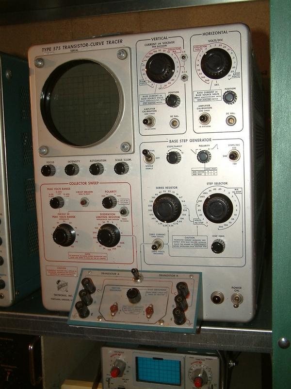
The old instrument can load the test transistor up to 400 Volts, up to 200W power. It will draw the complete curves family on the screen, well calibrated.
All currents are well limited, but a wrong setup can burn the transistor in seconds, so the study of his manual is strongest required before using it for a test. There are 2 sockets to compare A with B simply by using the switch between
575 is sometimes to find in the bay and on ham markets. It requires a lot of space, it is warm and heavy, but still a greatful helper in match and selecting transistors.
It have a brother, Type 570, this do the same with tubes.
greetings
Martin
The old instrument can load the test transistor up to 400 Volts, up to 200W power. It will draw the complete curves family on the screen, well calibrated.
All currents are well limited, but a wrong setup can burn the transistor in seconds, so the study of his manual is strongest required before using it for a test. There are 2 sockets to compare A with B simply by using the switch between
575 is sometimes to find in the bay and on ham markets. It requires a lot of space, it is warm and heavy, but still a greatful helper in match and selecting transistors.
It have a brother, Type 570, this do the same with tubes.
greetings
Martin
