• The move to the new server is done. There are some software and database maintenance updates in process. This has us passing the hat around to help out. We appreciate any donations. Seriously, even a dollar helps. The payment page may be found here - https://www.audiokarma.org/support.html

BMS Drivers

Break in

Anyone noticed any "break in" effect on BMS drivers?

As I never play anything too loud at home I tend to think if there was such a discernible break in, it would take a long time.

Curious because of the mylar construction.

Nothing scientific to report on my end. :scratch2:
 
Zilch,
I am using my BMS 4552NDs on Eighteen Sound XD120 waveguides, on top of my LE8TH woofers. Running active at 1.6kHz and using your BMS 4550/4552ND compensation filter worked out for PT Econoguide. I am finding this combination to work very well and I am considering putting all this into one box, or perhaps upgrading the waveguide to XT1086.

Anyway, I have 2 questions:
-I have a protection cap (33uF) right in front of the driver. Good spot or should it be in line prior to the compensation filter?
-About to put in the 19kHz notch filter you designed. When running active, you recommended placing that after the comp filter. I will do that but I'm not sure if that will interact with the protection cap following it just ahead of the driver.

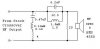
The notch filter is the .47uF/.13mH/4Ohm in parallel with the driver:
attachment.php


http://www.eighteensound.com/index.aspx?mainMenu=view_project&pid=22

http://www.eighteensound.com/index.aspx?mainMenu=view_product&pid=178
 

Attachments

  • ZilchMod 846B Circuit.jpg
    ZilchMod 846B Circuit.jpg
    10.4 KB · Views: 484
I put the 33 uF right at the amp output.

If you're running active, a series notch filter such as the 19 kHz one will do nothing without impedance ahead if it to work with. It's a shunt to ground, and the amp will just crank up its output to compensate; the 33 uF provides the necessary impedance. I puzzled over this many times before Earl switched on the light for me.

The circuit you show was designed to work with the stock crossover in front, which also has finite impedance. It's been a while since I worked with this, but the tank filter doing the HF comp may provide enough, as well, though I do recall swapping the series notch behind versus ahead of it, depending upon what was driving.

The XT1086 has killer specs; I'm embarassed to say that I have only done minimal testing with it. I intend to put them in some AR1s here, but I suspect the AR 12" woofer will not play to 1 kHz gracefully; AR lowered it to 575 Hz in AR3a.
 
Last edited:
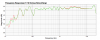
Thanks Zilch. In the graphs below I moved the notch filter fore and aft. I also removed or switched the location of the 33uF, but that aspect of the test I can't remember. I guess I might need to do this again. However I can't see much of a difference w/ notch filter in vs. out....

Red is notch filter inserted just before driver.
Blue in no notch filter.
Running the notch prior to the comp filter is about the same.
Of course I could be doing something stupid....

If you get to work more with the 18 Sound, please post your results.
 

Attachments

  • 4552ND_18snd_notch.png
    4552ND_18snd_notch.png
    52.3 KB · Views: 40
The spike is definitely there, which you were not previously able to show, so that's progress. ;)

I don't know why the notch isn't working for you, particularly if you now have the 33 uF ahead of the works, at the amp output. :dunno:

Here's my sinusoidal of that combo from over two years ago:

attachment.php

It looked even better on RTA:

attachment.php

"You saying you can make AR4x sound like that, Zilchster?"

"Better'n just about anything, actually."

Sounding mightily good in any case, I betcha.... :guitar:
 
Last edited:
VooDoo

I think this combination of waveguide/driver is real nice. Is this what ur using for the ARs? Will have to check those threads. I'd like to get one of those boxes myself, because I can't make a box living in the shoe box. Plus no skills.

I have no idea why I can't get the notch filter to do anything. I moved my protection caps to the amp. I tried the notch ahead of and behind the compensation filter. No luck.
:dunno:
BUT....

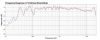
I misread my perfboard and have been inserting the comp. filter BACKWARDS. It has a modest effect on the curve, red is normal green is backwards. Any problem running it reversed? Green curve is flatter. No notch filter. This effectively puts the 20 Ohm parallel resistor before the compensation.
attachment.php
 

Attachments

  • BMS:18:comp:ForwdVsBackwrd.png
    BMS:18:comp:ForwdVsBackwrd.png
    46 KB · Views: 155
Hi

Yes , as Zilch mentioned a series LCR ( across the driver ) must have resistance between it ( the filter ) and the source / to be able to pull the impedance down ( & attenuate ) .

- If you'll do the math / you'll realize that this is the electrical rule you've twice violated .

- The capacitance reactance of a 33 uF cap at 19Khz is ???? ( not much / ie; 0.2538 ohms ) .
- Capacitance Reactance is measured in Ohms (R)

R = 1 / ( 2 * Pi * Frequency * C )
Frequency is stated in cycles
C is stated in Farads ( so divide your uF cap value by 1,000,000 )


- Zilches' parallel Tank Trap is a frequency dependant notch / & once again , by 19K it's inline resistance is ???? ( again not much / though it is dependant on the "Q" of that LCR ) .

- To test your series notch filter , put an 8 ohm resistor inline with the driver ( just after the 33uF cap ) with both notch filters after the inline resistor . You should get a working notch filter now ( though the Q is likely wrong ) .

>< cheers
 
Last edited:
I think this combination of waveguide/driver is real nice. Is this what ur using for the ARs? Will have to check those threads. I'd like to get one of those boxes myself, because I can't make a box living in the shoe box. Plus no skills.
Yeah, AR4x.

http://www.audiokarma.org/forums/showthread.php?p=1534352&#post1534352

There should be plenty of them where you are, Freecycle or $20 max at thrift shop/yard sale. What do they call that there, dumpster sale? ;)

This effectively puts the 20 Ohm parallel resistor before the compensation.
20 Ohms tames the impedance peak of the driver; gotta be directly across it to help the comp filter behave more predictably. Your curves are showing that difference. It's a frequency nonspecific gratuitous lamer Zobel; JBL uses it routinely with compression drivers.... :tongue:
 
Last edited:
OK, Zilch and Earl, sorry for the trouble.
I added an 8 Ohm non-inductive series resistor between the protection cap at the amp and the head of the parallel tank trap circuit. I placed the series notch in parallel between the resistor and the tank trap.

I am now able to get about 2-3 dB attenuation off the peak of the spike. Blue is no notch. Unfortunately, I bumped the volume knob apparently, so I've got a small offset.

Thank you for your info, Earl. I now assume the reason the series notch is not working as expected for me is because the passive crossover it was designed for has a very different impedance from the 8 Ohm resistor I am using that the notch interacts with. So until I learn more about this, I might also assume that the Q may have broadened a great deal, making the notch a broad bandpass filter or perhaps it went the other way and gotten so sharp that a slight frequency offset brings most of its attenuation out of range.

Obviously, I'm going to have to learn to work with this if I decide to keep using these drivers in an active system.
 

Attachments

  • Notch w: 8 ohm at amp.png
    Notch w: 8 ohm at amp.png
    50.7 KB · Views: 30
sw-r said:
Thank you for your info, Earl. I now assume the reason the series notch is not working as expected for me is because the passive crossover it was designed for has a very different impedance from the 8 Ohm resistor I am using that the notch interacts with.

- Series LCRs above 10K are really tough to finesse . As a rule ( & because my hearing only goes to 13K ), I stay away from trying to make them work within this octave.

Anyways:
- The working loop impedance ( formed between the series resistor & the driver ) dictates the maximum amount of attenuation available for this type of notch. Other "R" factors come into play / but this is the main one .

- To identify the maximum attenuation available for your LCR within any given circuit / simply omit the resistor ( of the series LCR ) / and then remeasure & look at the FR .

- To finesse the notch depth / start by adding any resistance ( that's greater than 0 ) but less than what the present value was that you first tried .
- Then remeasure & try again .

>< cheers
 
Last edited:
I hate to suggest it, because it becomes more complex, but it may be that your amplifier source is "stiffer" than what I use when biamped, which is the Sonic Impact T-Amp. Also, by adding a resistor in series with the main line, you are in effect making an L-pad, not a bad approach to providing the requisite impedance with which the series notch can work, but it also introduces more variables.

The notch was indeed optimized for use with the Altec N800 passive highpass, and as Earl suggests, I do recall that small variations in component values make big differences when designing a high-Q notch in this region.... :yes:
 
Now I'm beginning to realize that this is the same reason I have not been able to get a woofer Zobel to work in an active system, because the source impedance of the amp is very low and there's nothing in the loop impedance for it to work with. Wow.

That gets me thinking about whether or not the 20 Ohm quasi-Zobel in parallel with the HF driver will have the intended effect when run active.

I will try to measure the impedance with Fuzzmeasure to see if I can, and what is going on.

Thanks for clueing me in on how to adjust the notch depth.
:thmbsp:
 
Resurrecting an old thread. I've a pair of BMS 4552 coming to mount onto my Altec 811b horns. This is a bi-amped system, signal coming from a 24dB/octave active crossover.

There has been lots of mention of T filters, Tank filters, and a 18.5 kHz notch filter needing .33uf somewhere in the circuit.

Anyone here up on the latest recommendation of circuitry? Any help will be greatly appreciated.
 
Resurrecting an old thread. I've a pair of BMS 4552 coming to mount onto my Altec 811b horns. This is a bi-amped system, signal coming from a 24dB/octave active crossover.

There has been lots of mention of T filters, Tank filters, and a 18.5 kHz notch filter needing .33uf somewhere in the circuit.

Anyone here up on the latest recommendation of circuitry? Any help will be greatly appreciated.

This is pretty much what I am doing now with my Altec 9844-8Bs. I run a Behringer DCX2496 to a Crown PS200 for the LF and a chip amp for the HF. The input of the DCX is fed digitally by a Behringer DEQ2496. I am using the EQ to handle compensation for the BMS 4552ND. The crossover of course handles the crossover, but also time delay between the LF and HF. The system works very well.

As an aside, I made some adapters to mount QSC 152i waveguides on that speaker. I may try it with both Altec 902 and BMS 4552.

I believe I have measurements of the BMS on the active system. If I find them I will link or post here. I do not believe you will need a notch, and I don't think that it would work active, anyway.
 
Last edited:
Boy, that sure looks nice active. My crossover is a TDM 24CX2. I'll be running my 811b/4552 from 6500Hz to 20kHz. The smallest amp I have is a Carver PM300, it's 100 wpc. Total overkill, all I really need is probably a 1 wpc tube amp for my HF component.
 
Back
Top Bottom