• Please note that Audiokarma will be offline briefly for updates early on Monday morning, September 28th.

BOFA V60 TUBE AMP (B&O PRO DEPARTMENT)

Subchannel

Active Member
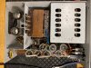
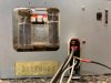
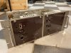
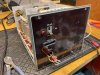
I bought a while back 2 dual mono tube amplifiers made by B&O professional department for sound and cinema. These are 4 monoblocks of 60w each, 20ohms load.
I have now tested one of them with a variac and a resistor on output. All tubes are glowing ( 2 x ECC83, 2 x EL34 (modified from KT88).
Tried with signal and speaker, and the meter in front works so it is signal in, but the speaker is dead silent.
Connected the speaker to pin a3 and earth, and signal on a1 and earth.
Can anyone here guide me to which pins on the output transformer to connect the speaker?
(yes I know it´s not good to turn on tube amp with no load on output, but the signal was very weak so I hope the transformer is ok)
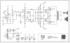
Please see link for large schematics.
Thank you in advance!!

http://www.analogbo.dk/diagrammer/Bofa_V60.jpg

udg = output
indg = input
 

Attachments

  • IMG_4183.jpg
    IMG_4183.jpg
    130.7 KB · Views: 85
  • IMG_4185.jpg
    IMG_4185.jpg
    140.4 KB · Views: 79
  • IMG_4187.jpg
    IMG_4187.jpg
    91.1 KB · Views: 76
  • IMG_4188.jpg
    IMG_4188.jpg
    118.7 KB · Views: 75
Register to hide this ad
so you run Bofa deez amps?

(sorry)


looks like negative to 3A, and positive to 4A. There is a switch that needs to be in the right position, appears to switch from 100v to 20v mode. 20v is probably about 6 ohms, or close enough to "normal" speaker loads.
 
Hehehe!
Thanks for the reply (again) Gadget73. Was hoping you caught this!
The switch is for 100V system or (normal) 20ohm output. Not a very usefull impedance for speakers nowadays. Found some info on danish site hifi4all (Google translate):


Bofa V60

I start with the Bofa V60 ... this amplifier is of course equipped with both EL34 and KT88. However, I want to justify why it works best with KT88. It is an amplifier for 20ohm operation. I have measured the output of the output transformer Ra-Ra to 6Kohm, and this relatively high impedance helps to operate 8ohm, which many use it for, and at the same time helps the larger allowable current at KT88, so it can deliver 28W / 8ohm at 1% distortion ... EL34 only handles half.

It has 2 feedback loops ... in the first is a 100pF capacitor ... it needs to be removed ... thereby correcting an otherwise hopeless frequency response somewhat

Does this make any sense Gadget73?
 
guessing they're talking about the 100pf cap from plate to cathode on the second triode? That does form a local feedback loop at that stage, the cap and the 100k resistor are in parallel. The cap would create more feedback at higher frequencies, so it would tend to roll the highs off. Exactly how much I don't know, but it could be enough to make it not sound good. On the other hand removing it totally might extend the HF response enough to where the amp wants to be unstable so it would probably be a good idea to do some square wave tests. Possible the best answer is somewhere between 100pf and no capacitor.


I was thinking that was 20 volts, which seems like a more reasonable value for a distribution amp. A lot of US ones would do 25 or 70 volt output. 20 ohms is just strange. The 100v matching transformer may be the better answer here, should get more power output at least.
 
Thanks again Gadget, your info is really helpfull for a tube amateur. That worked. Output on a3/a4 and input on a1/ b1.
It plays beautiful the fist 30seconds, then starts to distort a bit (very audible) and clicking noise/ spikes appears with few seconds appart, and some hum. Guess removing the shady switch for the 100v system, better tubes and new caps would help after 60 some years.
I will test it on my scope.
 
can you measure the plate and screen voltages? Quite possibly some other primary impedance makes more sense. 6k seems high for EL34 or KT88.

any output transformer change would involve messing with the feedback circuit too. This can all get fairly involved.
 
When looking at pinout on f.ex EL34, is this from top or bottom view of tube? ( yes I know, many newbie questions here)
 
Plate voltage is aprox 116VAC, screen is 20.5VAC. (pin 3 and 4).
Amp is not earthed from variac, is that a problem?
 
Last edited:
earth won't matter on this

Voltages will be DC. Guessing something like 600 at the plate and about half that at the screen. Be very careful where you poke in here, its going to have some nasty voltages inside.

just as further confirmation, pin 3 should have a wire going to the transformer, pin 4 will have a 1K resistor. 3 is the plate, 4 is the screen.
 
About 12VDC on plate and almost nothing on screen. That´s not right. When connecting the DMM ( brand new Fluke) probes on pin 3 and earth/ chassis, something mechanical is oscillating, like a screaming doorbell/ sinewave.
The amp is playing, and qiute loud (though distorted) so I probably do something wrong.
 
doesn't actually look like circuit negative ties to chassis on this. Try meter - to 2A on the output jack. That should give a result.

a jumper from 2A to 4B would put the chassis at circuit ground, but I don't know if that might cause other goofy problems.
 
And if to use these as original with KT88, what to look for if they are modified? Or could it be the former owner just put EL34 there without doing anything?
I have not found any components that differ from schematics.
 
Back
Top Bottom