• The move to the new server is done. There are some software and database maintenance updates in process. This has us passing the hat around to help out. We appreciate any donations. Seriously, even a dollar helps. The payment page may be found here - https://www.audiokarma.org/support.html

BOFA V60 TUBE AMP (B&O PRO DEPARTMENT)

From site:

"The V60 was one of the last valve amplifiers from BoFa. The V-series from the 1950’s included a small EL84 PP called V15 and a high power version model V120. ( The valves used in this, is unknown at the time of writing ) .

Most vintage schematics from B&O insisted on Beyschlag resistors and Telefunken tubes. I pretty much learned the same thing in the 1980’s. Jørgen Schou was the primary supplier of transformers to B&O, this guarantees the quality of the iron and makes it worth to modify these beautiful amplifiers. All three amplifiers in this vignette was supplied with a EM84 magic eye for signal monitoring. The 5 Ω resistor at the cathodes of the power tubes, was used for measuring/monitor purpose."
 
yeah that sounds more like what I'd expect. Big power amps use a lot of voltage. My Bogen 100a's run about 700 on the plate and 350 on the screens. Its not something you want to get across.

anyway, I'd expect it to want less negative voltage at the grids to get to the same idle current with an EL34 vs a KT88. I plugged some numbers into a load line calc and it says for 55ma of idle current with a KT88 at those plate and screen volts, you need -27.3 volts, but with an EL34 it needs -17.8 volts. At 25ma its -36v vs -22v. No clue what this is actually idling at, its just a couple of numbers picked out of the air. What that also means in a practical sense is that a driver circuit for a KT88 can run an EL34. Grid to grid voltage is basically double what the bias voltage is, and since the EL34 needs less bias voltage, that means it needs less signal drive to reach full output power.

if you want to know what they idle at, voltage at pin 8 would get us to that answer.


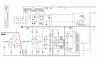
I don't exactly know what would need changing with what appears to be a bias regulator arrangement. Thats what those two transistors are doing. It should be looking for a target voltage drop across those 18 ohm resistors, and it doesn't specifically care what the grid volts are to get there. Its possible nothing needs to be done in order to make it work with a different tube though. If you wanted to change the target idle current, changing the value of the cathode resistors would get it there. The circuit would aim for the same voltage across them, but changing the resistor would mean that actually lands at a different amount of current.
 
Djises you know your **** Gadget, if I knew half I would be more than happy.
Thank you once more for extremely good information! I actually learn a lot from this, and it’s a lot of fun.
I will do some more testing. I have a VTL Stereo 90 (not mine) that I can borrow KT88’s from.
I will thoroughly compare schematics with amp to see what, if anything, is modified.
Have a lovely weekend for now!
 
Found some more info on a Danish site (again, Google tr.):


As we talked about, you can use the V-60 with the EL 34 at the end without changing anything.
But for the automatic bias control to work, a few resistors need to be changed. (see diagram)
The 25 ohm cathode resistor can be made of a 10 ohm and a 15 ohm resistor in series. It should be ½ Watt types.
Without changes, the circuit can not "screw further up" for the idle current, only down. This is a problem as the tubes age.
A V-60 with EL 34 instead of KT 88 at the output will also give a slightly smaller output power. Approx. 40 W
 
Back
Top Bottom