

You are using an out of date browser. It may not display this or other websites correctly.
You should upgrade or use an alternative browser.
You should upgrade or use an alternative browser.
Bought a Sony TA-N7, and now?
- Thread starter Harolda
- Start date


or can they be cleaned?
You can clean the contacts but it's hardly worth the effort since the newly exposed metal oxidizes faster than before; better to just replace and be done with it.
The interesting thing about the TA-N7B is that there are 4 relay contacts in parallel per channel so it would seem that you might have something else that's responsible for your intermittent channel like perhaps the volume control needs cleaning.
Do you know a source for the relays?
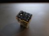
From its foot print on the PCB it looks like the relay is a 4PST type ...
Have you pulled 1 to see what's marked on it?
Last edited:

Harolda
Well-Known Member
From its foot print on the PCB it looks like the relay is a 4PST type ...
Have you pulled 1 to see what's marked on it?

No not yet, i plan to do that this week if posisble. To busy at my company
Harolda
Well-Known Member
A 4PST is just a 4PDT with the NC leads clipped off.
Echowars, i see that 4 pins have been clipped off. Are these the NC leads you are referring to?
Harolda
Well-Known Member
Now i stop the dismantling of the thing, last replacement are the speaker relays. I also mounted new binding posts and rca sockets, since the old ones where loose or broken.
So what did i do (or what do i plan to do when rebuilding):
- all fusibles
- large PSU caps
- all electrolytics
- double diodes --> two single diodes in series
- bias and offset adjustment pots
- kapton insulation for vfets and the 2sc1173 and 2sa473
- New 2sc1173 and 2sa473
- rca & speaker binding posts
- cleaned inside
- reflowed all the solder joints
- speaker relays
Will do the same to my second amp, when this one is playing. Already ordered some of the parts in the required quantity.
I am wondering if i need to put thermal grease on the insulation sheets. The originals did not have any thermal grease. When building my own (LM4870) power amps, i used the thermal grease on both sides of the kapton sheets.
I will post some pictures this week with the new rca and binding posts.

<snip>...I am wondering if i need to put thermal grease on the insulation sheets. The originals did not have any thermal grease. When building my own (LM4870) power amps, i used the thermal grease on both sides of the kapton sheets.
I will post some pictures this week with the new rca and binding posts.
Yes, do this again.
DO post pics - we all like pics :thmbsp:
I will post some pictures this week with the new rca and binding posts.
:yes:


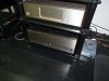
Harolda
Well-Known Member
Very nice!
So are you liking what you hear in your second TA-N7?:yes:

Yep, like it a lot. I do not dare to take it to high levels, as it was not checked at all yet. And remember that i bought it as defect (one channel no sound), but it plays fine on both channels. In the beginning it gave me some problems indeed on one channel at low volumes.
I did not open it yet and also did not measure the bias voltage, but the thing is not getting warm at all.
regards
I do not dare to take it to high levels, as it was not checked at all yet.
I understand completely. No need to cause unnecessary damage.
Harolda
Well-Known Member
I found some time again this week to work on the beast.
What did i do:
- new loudspeaker relays
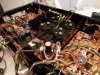
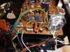
- mounted the pcb's to the housing. In the original TA-N7B there is a piece of foam under the pcb, i think to support it, as one side of the pcb is floating. I found some nice foam that could do the job. But i added a thin sheet of plastic on top of the foam to avoid contact of the foam with the PCB. I will also need to put a piece of foam on the loudspeaker relay, to support the pcb in the opposite direction. This was also done in the original amp. The first picture shows the piece of foam under the pcb.
- tried to achieve original routing for the wiring as much as possible
- mounted the large PSU caps. I rotated them slightly, such that the copper bar can fit again. The only problem is the size of the thread used on the new caps. It is larger than for the original caps. So i would have to increase the size of a lot of holes. Other option is to use a threaded stud which converts it to the old thread again.
- Wiring is soldered to the new cinch plugs.
- Test installation of the heat sinks.
to be continued.
Attachments



MX117.MC7150
Listener
Nice work. The TA-N7 was certainly a 'tour de force' by Sony. Is always nice to see the physical layout of older amps/receivers/etc., VFET and not, as the design was done by hand, being before the age of CAD.
The only problem is the size of the thread used on the new caps.
I wonder if you could use a heli-coil to make up the difference in thread sizes? Maybe there's a suitable size available. :scratch2:
to be continued.
