
• The move to the new server is done. There are some software and database maintenance updates in process. This has us passing the hat around to help out. We appreciate any donations. Seriously, even a dollar helps. The payment page may be found here - https://www.audiokarma.org/support.html

Braun SK-55 (Snow Whites Coffin) high current issues - dim bulb

marczee

Member
Looking for some guidance since I've hit a wall with my dim bulb tester. I have limited experience with tube radios and foreign makes.
I have a Braun SK-55 "Snow Whites Coffin" that started popping fuses after plugging in the turntable power. I've replaced out of spec caps and resistors as I started to trouble shoot through the circuit, which doesn't help the issue.
I get major current draw (dim bulb on) with tubes out, all trees in B+ disconnected (downstream of both 50mf main filters).
The main filter caps test ok (50/50mf), I also bypassed with known good 50mf caps to no avail.
I was able to send a signal gen through the output transformer and it came out of the speaker, while unpowered. (still could be bad??)
Power transformer works as it should at 110vac tap, as well as the turntable motor, with the downstream audio/radio circuit unconnected. Filament voltage A-OK.
Like other Brauns, this one does not have a bridge rectifier but a single .0022 cap (replaced with OJ) and an SH-1 diode, which was replaced with a UF4004. (Would a bridge rectifier be better?)
No appearance of speaker mis-wiring.

I'm left at this output transformer, is there a good way to test it? I might actually have an old American make SE el84 output transformer that could probably be used. I don't see anything available online that resembles a Braun original. I would probably have to be in Germany to find something.
Thanks for looking! - - -

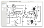
SK55.png
 
Register to hide this ad
half wave rectification? Why?

unfortunately you can't sub that with a bridge in any easy way, the voltage would end up way too high.

anyway, caps in these don't so much tend to fail off value as with excessive leakage. If its drawing high current with the tubes out and the diode itself isn't shorted, the first cap is questionable, so is the 50uf wired to the EL84 screen. If by bypassed it you mean you clipped another across the original, that won't do anything to resolve an internal leakage problem, you'd have to disconnect it entirely.

output transformers rarely fail shorted to ground, but an ohm check would rule that out easy enough. I did once have one that read OK to ground but with about 100 volts on it, the thing started to arc to the frame.
Bypassed the old dual cap completely - with 2 separate 50mf/450v caps.
I did see that on the Braun RT20, which seems to be the SK55 minus the turntable, that is has a bridge rectifier.
Braunrt20.png
 
so it still draws a lot of current even with no tubes and new caps installed?

try unhooking the cap from the plate of the EL84 to ground.


a bridge is the better way but the voltage will be about 1.4x the AC input voltage, with a half wave its about 0.7x so basically if you stick a bridge in there the voltage will be double.
Still no luck lifting that cap from el84 plate.
 
As soon as I connect that first 50mf cap to the half wave rectification, bulb full on. I get 205vAC at that point.
 
if there is nothing else connected besides that first cap, that says cap problem to me.

It shouldn't be AC across the cap unless the diode or the cap across it is shorted either.
 
if there is nothing else connected besides that first cap, that says cap problem to me.

It shouldn't be AC across the cap unless the diode or the cap across it is shorted either.
It looks like the diode is shorted. C 413 is not shorted? Is the first 50 mfd cap wired in correctly?

Try another diode. Use an appropriate sub. Good luck! :)
 
if there is nothing else connected besides that first cap, that says cap problem to me.

It shouldn't be AC across the cap unless the diode or the cap across it is shorted either.
Yes by completely disconnecting everything right after of the diode / cap hw rectifier, no lit bulb, 200~vac, DC does not read, only "overload" on meter. Add only the first 50uf filter, bulb on, and then 8vdc at that point. Correct me if I'm wrong, should I only be able to get DC after that first filter stage, or does it appear before that at the end of the diode / cap rectifier.
 
Yes by completely disconnecting everything right after of the diode / cap hw rectifier, no lit bulb, 200~vac, DC does not read, only "overload" on meter. Add only the first 50uf filter, bulb on, and then 8vdc at that point. Correct me if I'm wrong, should I only be able to get DC after that first filter stage, or does it appear before that at the end of the diode / cap rectifier.
You should get ~230 VDC at the first cap (50 mfd).
 
It looks like the diode is shorted. C 413 is not shorted? Is the first 50 mfd cap wired in correctly?

Try another diode. Use an appropriate sub. Good luck! :)
Thanks - I subbed a UF4004, seems like that is possibly my best choice. I'll just put a new one in, this one beeped out as good on my meter.
 
that cap is probably fried at this point if its been subjected to that much AC.

the diode isn't backwards is it? Cathode should go to the + side of the cap. Negative of the cap to ground. The other end of the transformer also needs to go to ground.


what range is your meter on? Unless its set less than 200v it shouldn't give OL.
Diode WAS in fact bad, I put in a new one.
Nothing's backwards.
Everything works now as it should, very small glow on dim bulb. BUT, if I go into wall power, fuse blows, and diode blows on original filter cap can. I'm down to one last UF4004, so I'm going to try wall power with my subbed caps. Though they have been subjected to that AC as well at this point. Either way, worth a try, I'll just order some more diodes and a better main filter cap situation, they are just cheap 47/450 Xicons..
The first replaced diode in there passed the beep test, but has a reading both ways. The second diode now measures a straight short. Caps have always tested good for value and leakage on a nice Sencore cap tester, but I'll just replace them at this point.
 
It looks like the diode is shorted. C 413 is not shorted? Is the first 50 mfd cap wired in correctly?

Try another diode. Use an appropriate sub. Good luck! :)
A new diode works, thanks. I need to remind myself that the new replacements I'm using need attention also. Still something drawing current. Diode and 500mA fuse blows at power up from wall AC.
 
I can, that was definitely one of the first things I noticed, the lamp holder was shorting out against the chassis. I added a bit of shrink to help.
I'd methodically follow the electricity's path and rule out parts, connections, solder points, wiring, and any path the electricity should and should not take.

Untitled-1.jpg
Concentrate on this part of the circuit. Go from left to right, ruling out shorts.
 
Last edited:
I'd methodically follow the electricity's path and rule out parts, connections, solder points, wiring, and any path the electricity should and should not take.

View attachment 3497387
Concentrate on this part of the circuit. Go from left to right, ruling out shorts.
Parts ordered, we shall see. German screw end cap, and some more diodes. Plug to power transformer secondary voltages are A-OK. No apparent shorts. Changed the Earoplug to a polarized Edison plug while I was at it.
 
Last edited:
Parts ordered, we shall see. German screw end cap, and some more diodes. Plug to power transformer secondary voltages are A-OK. No apparent shorts. Changed the Earoplug to a polarized Edison plug while I was at it.
Also, check all solder points and circuit board tracings (if it has a board in the power supply section) for shorts and damage. I like using this to help.

Good luck! :thumbsup:
 
Also, check all solder points and circuit board tracings (if it has a board in the power supply section) for shorts and damage. I like using this to help.

Good luck! :thumbsup:
Well, no luck. OK on dim bulb, tiny amount of glow. Plug into 117vac, fuse and diode pops. New can dual cap, new R20 1.5k 2w.
 
Back
Top Bottom