
• The move to the new server is done. There are some software and database maintenance updates in process. This has us passing the hat around to help out. We appreciate any donations. Seriously, even a dollar helps. The payment page may be found here - https://www.audiokarma.org/support.html

Brian's AU-555 restoration

Brian1970

AK Subscriber
Subscriber
I'm pretty new at this hobby but was curious about the early Sansui "tube-like sound" so I found this AU-555 and took a chance on it. I plan to do a restore on it and apply some of the upgrades leestereo documented so nicely in his 555A thread.

It's in pretty original condition as far as I can tell. Somebody did replace one of the fuses with one that's too long for the holder as you can see. The coating of dust was very even before I wiped out some of the dead spiders so it looks like this one got put away and forgotten at some point. I'll be glad to get it working well again.
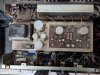
PXL_20230403_171709338.jpg

I put it on a DBT and that went well. Checked for DC on the speaker terminals and there was none, so I hooked up some speakers. That went about like you'd guess. Switches and Pots were very dirty. Cleaned those and I'm a little amazed at how great it sounds. I've been letting it play some music for a couple hours and I'm almost tempted to leave it alone for a while. This may be a slow-motion restoration.

With no input, turning the volume up reveals some noise/hiss. I assume that could be due to noisy transistors? Apparently that wouldn't be surprising on these from what I've read on them so far. I'll have to do some research on good substitutes to add to my capacitor order. At lower volume though, the noise isn't audible.

Also noticed with the volume up all the way, it's receiving a radio station. I've got some broadcast towers pretty close to me and all the shields are off so I'm not going to worry about that too much yet.

I think the next jobs on it will be to blow out all the dust and run through the service manual alignment. If anyone has ideas for other things to check, please let me know. And if anyone would like to follow along, I'm new at this so I appreciate any help.
 
Register to hide this ad
Great score I’d replace the 2sc458 transistors they are known to fail and can cause damage to other components if they fail might even reduce some of that hiss :) ksc1815 is the substitute you need
Thanks for that advice. Looks like there are quite a few of those 458's in it.
 
I think you may have a little gem on your hands, you are going to love it.

My 555a also had a little hiss even after a recap/restoration, a pair of shorting plugs on one of the set of phono inputs cured the noise. May be worth keeping in mind if all else fails.
 
I think you may have a little gem on your hands, you are going to love it.

My 555a also had a little hiss even after a recap/restoration, a pair of shorting plugs on one of the set of phono inputs cured the noise. May be worth keeping in mind if all else fails.
It's great so far. I've been letting it play background music here in the home office the past couple days and it sounds pretty great now. Not sure the recap will do anything for the sound quality but I'm sure it needs to be done just to avoid problems. Those ELNAs are 50 years old after all.
 
It's great so far. I've been letting it play background music here in the home office the past couple days and it sounds pretty great now. Not sure the recap will do anything for the sound quality but I'm sure it needs to be done just to avoid problems. Those ELNAs are 50 years old after all.

It is hard to say how much a recap will improve the sound some capacitors really manage to hang in there even after 50 years, but it is hard to imagine that all the components are still in spec, The few 517's/717's I have recapped benefitted a lot but they were not great sounding before the recap in comparison to afterwards.
Leestereo's upgrades really do improve things as well.
Good that you are using it and enjoying it already, and the more you listen to it now the better to judge any changes if you do recap it.
 
Remember it took 50 yrs for those caps to "sound" the way they do. All of the ones I have fully rebuilt have a different sound afterwards. Definitely not as warm sounding and mid bass lost it's punch. The 661 I just finished, it was nice after rebuilding the driver board. Went on to the preamp and PS, it pretty much lost all the warmth. I really should have stopped with the driver board. Most all of the small value caps checked had high ESR, and over the rated uF values. On the phono input a coupling cap when checked, the test meter determined it was a resistor. Weird that it sounded good when stock.
 
Remember it took 50 yrs for those caps to "sound" the way they do. All of the ones I have fully rebuilt have a different sound afterwards. Definitely not as warm sounding and mid bass lost it's punch. The 661 I just finished, it was nice after rebuilding the driver board. Went on to the preamp and PS, it pretty much lost all the warmth. I really should have stopped with the driver board. Most all of the small value caps checked had high ESR, and over the rated uF values. On the phono input a coupling cap when checked, the test meter determined it was a resistor. Weird that it sounded good when stock.
Never thought about aging capacitors like fine wine but maybe there's something there. :) Not sure exactly when mine were made but it was apparently a great year for ELNAs.
 
Never thought about aging capacitors like fine wine but maybe there's something there. :) Not sure exactly when mine were made but it was apparently a great year for ELNAs.
This is very subjective, but that warm sound many attribute to vintage amps may be due to worn components. I personally think that some of the amps I restored sounded muddy to me. After restoration, the sound was much brighter, but also much cleaner sounding - to my ears. Having said that, I'm mainly referring to amps from the late 70s. I cannot comment on early 70s designs, which often had a quasi-complementary design and were capacitive coupled.
 
Agree this is very subjective but I do agree that after each recap I do the warmth is somewhat lost... I like to think this is how the amp originally sounded, we associate the warm sound with old electronics but when it was new the designer didn’t see the unit as old and vintage…electrolytic capacitors have a limited lifespan as per their own manufacturer data sheets, generally 20 years tops so in my view best to recap for reliability and improved sonics
 
Last edited:
Agree this is very subjective but I do agree that after each recap I do the warm is somewhat lost I like to think this is how the amp originally sounded we associate the warm sound with old electronics but when it was new the designer didn’t see the unit as old and vintage…electrolytic capacitors have a limited lifespan as per their own manufacturer data sheets generally 20 years tops so in my view best to recap for reliability ol and improved sonics
I do plan to replace them. In fact, I just placed the order for all the new caps and various other parts I need. It's already been a fun project. Spent some time last night researching what kind of capacitor I need to replace the 600V oil cap on the power switch. If it's not a 630V film snubber cap, don't tell me.
 
The AU-555 and AU-555A are not identical. If you are following a 555A rebuild, there will be differences with yours. Be careful. Compare the schematics and veryify that any 555A parts list is the same as what you have in your 555.

- Pete
Thanks and yes, Ive figured out there are a lot of differences. Luckily, the 555A thread discusses some of the things that are different on the 555. You do have to read through the whole thing but there's a lot of great info in there, and on this site in general.
 
I do plan to replace them. In fact, I just placed the order for all the new caps and various other parts I need. It's already been a fun project. Spent some time last night researching what kind of capacitor I need to replace the 600V oil cap on the power switch. If it's not a 630V film snubber cap, don't tell me.
my understanding is you need a safety capacitor rated at that voltage with a classification of x2 but will let the experts confirm that.
 
my understanding is you need a safety capacitor rated at that voltage with a classification of x2 but will let the experts confirm that.
I spent a little time in that rabbit hole last night and from what I could tell looking at the schematic, it looked like a snubber and not a safety cap. But yes please, if anyone knows this for sure I would appreciate knowing.

Edit: Did more reading and looks like this should be a safety rated cap. Adding one to order #2. I knew there would be a second order.

upload_2023-4-4_18-17-51.png
 
Last edited:
Ugh. More time in the snubber/safety cap rabbit hole. The best I can tell, this cap is performing the role of a snubber but since it's connected to mains it needs to be safety rated (at least X1, and maybe preferably X1 according to something I read). So even though Mouser sells a thing called a snubber cap rated at the correct voltage, I should have read the datasheet more closely and seen it said, "not for connection across line". So I found a 250VAC, X2 rated, safety cap. Seems like the 600VDC rating is not really relevant for mains connection. It might imply it's good up to 250VAC but it's easier just to filter VAC ratings to make sure.

The thing that I'm wondering is that all the example snubber circuits I see like this have a resistor in series with the cap. So I was wondering if best practices have changed in the last 50 years and if I should put a resistor in there along with a new safety rated cap?
 
Last edited:
Snubber caps like the one linked, will allow a small amount of current to flow even when the switch is off. I don't believe that is what your looking for.

https://www.mouser.com/ProductDetail/Cornell-Dubilier-CDE/504M06QE100?qs=kwWuCeDmeqHtsfzFH90PSg==&mgh=1&gclid=EAIaIQobChMI0sryyf-S_gIVQyc4Ch2rQAauEAQYBCABEgJAbvD_BwE
I checked the datasheet on that one and it is also not approved for use across the line but there is a 0.1uF version in the datasheet that is, if used with a resistor in series. I guess that's to stop that small current flow? Which makes sense to me and is why I'm wondering how the AU-555 circuit only uses a cap without a resistor. Maybe overthinking it but if there's enough ESR in the original oil cap to serve the function and I remove that using a modern ceramic or film safety cap, am I creating a problem?
 
index.php

index.php


https://www.mouser.sg/ProductDetail/710-890334025006
I use above on my 777D , as stated below
https://audiokarma.org/forums/index...-a-sansui-au-777a.860863/page-2#post-12583215


Part 6: CHASSIS-MOUNTED CAPACITORS (MINIATURE) AND EXTERNALLY-MOUNTED TRANSISTORS


index.php


All input signals pass through a pair of coupling capacitors installed on the input selector switch itself. The stock 1µF electrolytic capacitors (C619/C620) were upgraded to 1µF stacked film types. The 0.033µF PIO capacitor (C001) that shunts the power switch was replaced a proper X2-Safety Class capacitor. The transistors (TR807-TR8814) installed on the rear chassis panel were unmounted, cleaned and reinstalled with new mica insulators and thermal paste.


index.php
 
Back
Top Bottom