• The move to the new server is done. There are some software and database maintenance updates in process. This has us passing the hat around to help out. We appreciate any donations. Seriously, even a dollar helps. The payment page may be found here - https://www.audiokarma.org/support.html

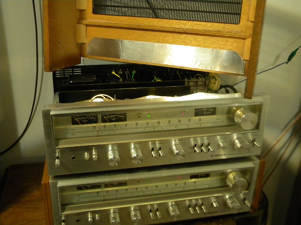
Brought home my new project - SX780

On the Emitter resistors, pull one side of each and oHm them out. You aren't looking for votlage, but resistance.

The 780/790 is really sensitive to "irish pennants" on the speaker wires. Cut the end clean, strip and twist 1/2" and solder ("tin") the end 1/2 of the wire to hold it together. Any stray filaments are the "irish pennants" and can cause shorting. And with new more sensitive STK's it doesn't take much to destroy one.

Larry
 
On the Emitter resistors, pull one side of each and oHm them out. You aren't looking for votlage, but resistance.

The 780/790 is really sensitive to "irish pennants" on the speaker wires. Cut the end clean, strip and twist 1/2" and solder ("tin") the end 1/2 of the wire to hold it together. Any stray filaments are the "irish pennants" and can cause shorting. And with new more sensitive STK's it doesn't take much to destroy one.

Larry

So basically, if I ohm them out and I get a tone, they are good? That's about the extent of my ohm-ing experience. Like, when you ohm out a fuse, if it's good, you get a tone that the signal is making a complete cycle. When there's a break, you don't.

And the ends just "pull out"? Just grab one post on each, gently pull and it will slide right out?

Thanks again for your help!!!
 
You are going to have to de-solder one leg of each of the resistors you want to test so that the reading will be accurate on the meter. The Desoldering iron I mentioned earlier will really speed up the process.

The beep function on a Multimeter is useful for quick continuity checks, not necessarily for testing the actual resistance rating of a component. When you are testing the resistor with one leg lifted, the meter may beep, or it may not beep, depending on what it's setting is and what the resistance is on the resistor itself. For instance, a good 1 meg-Ohm resistor will not usually make the meter beep, but the same resistor when it's bad and shorted through will! Go by the reading on the resistor/schematic to see what it's supposed to be and compare it to the reading on your meter, don't go by the "Beep"!

Hope this helps!
 
If the power output modules are removed there should be no need to lift a leg of the emitter resistor, since the only downstream connection is the module itself.

Try to manually select a resistance range (instead of autorange) and test with all power off. Resistance is supposed to be 0.22Ω.

I've read somewhere that below 1Ω, resistance is futile.
 
resistors should be 0.22 ohms set your meter on lowest ohms reading . maybe 200 ohms . touch leads together see what it reads .deduct this reading when measuring the ohms of the resistors .. the ohms you see when touching together your leads is the resistance of your leads .
bit more info there is a double diode in the module that goes bad . have seen it a few times now .not much you can do about it though except replace the module .
 
Last edited:
Excellent info/instructions guys! Once I got home and saw them, it made more sense. I should have a good opportunity tomorrow to dig in and take some measurements on those resistors.

If one or more of the resistors are faulty, will it mean a premature failure of the new power pack when I install it, or will it just not work at all, like when I got it?
 
just replace the bad resistors if you find any . its pretty likely new module will pop pretty quickly if not .
 
10-4 on that. One thing is for sure....there doesn't seem to be a problem getting parts for these receivers. If this one is successful as I hope it will, I will be picking up some more fixer-uppers....maybe start me a Pioneer museum. :D
 
I had a few minutes today, so I decided to try my first shot at cleaning the pots. Talk about instant gratification. The volume was the main culprit. With my little test, surround speaker hooked up, the volume was terribly scratchy when adjusting at any level. I cleaned them all and powered back up and was amazed at how well it worked. And it may be my imagination, but I thought it sounded louder at lower volume than it did before I cleaned it. It appeared louder at 3 after cleaning than it did just past half-way before I cleaned it. Maybe it had something to do with the pots being dirty, but I'll take it.

I'm bored waiting on these new power packs to arrive in the mail. I guess my next task will be to start cleaning it; pull the knobs and soak them as well as cleaning the face-plate. I've seen some good posts on this so I'll use some of that past experience on mine.
 
If you are bored you can still accomplish a few things:
  • Clean all the rest of the controls just as thoroughly;
  • Clean the DC offset pots so that they are ready for final setup with no surprises when the new modules get installed;
  • Study the bias and offset checks procedures so you are ready for final adjustment. Even though the bias isn't adjustable, it would be nice to know where it is for assurance;
  • Lube the tuner knob shaft, tuner VC shaft and gears (Carefully - Search for threads on that), and lube the dial cord guides;
  • Verify that the dial cord is strung on the drum sheave properly, and not overlapping, then apply wax to the cord;
  • Re-flow the solder joints at the main filter caps on the power supply board;
  • Re-flow the solder joints on the voltage regulator transistors, and closely inspect the foil circuit traces around their mountings;
  • Verify the main power transformer screws and nuts are snug, since they tend to loosen from thermal creep every 30-ish years or so.
  • Read the procedure on output power meter adjustment. You can use a CD player to inject the 1khz signal for testing. An audio test CD image file (binary ISO format) is available HERE and you can burn an audio test CD from it;
  • Assemble a dim bulb tester (DBT) for under ten bucks and be prepared to re-start your unit safely on 40W, 60W, and 100W lamps.

If you're REALLY bored you might want to make a couple of hot-rod mods so the unit is ready to go through its paces once it gets assembled, like this:

http://www.audiokarma.org/forums/showpost.php?p=4575031&postcount=12

Another thing I've found helpful on these models is to clean the interior of the plywood case near the front, then apply a piece of 2" duct seal tape (the thin aluminum foil type, not the old-fashioned canvas duct tape) as a heat and light reflector for the dial light bar. I had a couple of these actually get browning visible on the exterior of the case in the three spots where each dial lamp is positioned. The foil also improves the overall illumination of the dial face a bit. If you decide to do this, be CERTAIN the foil is stuck well, and maybe even apply some additional hot-melt or other adhesive as insurance, since you don't want a piece of conductive foil tape floating around inside your unit.

SX-780-HeatShield.jpg


That should fill a few of your spare minutes while you await hybrid module delivery.

 
If you are bored you can still accomplish a few things:
  • Clean all the rest of the controls just as thoroughly;
  • Clean the DC offset pots so that they are ready for final setup with no surprises when the new modules get installed;
  • Study the bias and offset checks procedures so you are ready for final adjustment. Even though the bias isn't adjustable, it would be nice to know where it is for assurance;
  • Lube the tuner knob shaft, tuner VC shaft and gears (Carefully - Search for threads on that), and lube the dial cord guides;
  • Verify that the dial cord is strung on the drum sheave properly, and not overlapping, then apply wax to the cord;
  • Re-flow the solder joints at the main filter caps on the power supply board;
  • Re-flow the solder joints on the voltage regulator transistors, and closely inspect the foil circuit traces around their mountings;
  • Verify the main power transformer screws and nuts are snug, since they tend to loosen from thermal creep every 30-ish years or so.
  • Read the procedure on output power meter adjustment. You can use a CD player to inject the 1khz signal for testing. An audio test CD image file (binary ISO format) is available HERE and you can burn an audio test CD from it;
  • Assemble a dim bulb tester (DBT) for under ten bucks and be prepared to re-start your unit safely on 40W, 60W, and 100W lamps.

If you're REALLY bored you might want to make a couple of hot-rod mods so the unit is ready to go through its paces once it gets assembled, like this:

http://www.audiokarma.org/forums/showpost.php?p=4575031&postcount=12

Another thing I've found helpful on these models is to clean the interior of the plywood case near the front, then apply a piece of 2" duct seal tape (the thin aluminum foil type, not the old-fashioned canvas duct tape) as a heat and light reflector for the dial light bar. I had a couple of these actually get browning visible on the exterior of the case in the three spots where each dial lamp is positioned. The foil also improves the overall illumination of the dial face a bit. If you decide to do this, be CERTAIN the foil is stuck well, and maybe even apply some additional hot-melt or other adhesive as insurance, since you don't want a piece of conductive foil tape floating around inside your unit.

SX-780-HeatShield.jpg


That should fill a few of your spare minutes while you await hybrid module delivery.
:thmbsp::thmbsp::thmbsp::thmbsp::thmbsp:
 
If you are bored you can still accomplish a few things:
  • Clean all the rest of the controls just as thoroughly;
  • Clean the DC offset pots so that they are ready for final setup with no surprises when the new modules get installed;
  • Study the bias and offset checks procedures so you are ready for final adjustment. Even though the bias isn't adjustable, it would be nice to know where it is for assurance;
  • Lube the tuner knob shaft, tuner VC shaft and gears (Carefully - Search for threads on that), and lube the dial cord guides;
  • Verify that the dial cord is strung on the drum sheave properly, and not overlapping, then apply wax to the cord;
  • Re-flow the solder joints at the main filter caps on the power supply board;
  • Re-flow the solder joints on the voltage regulator transistors, and closely inspect the foil circuit traces around their mountings;
  • Verify the main power transformer screws and nuts are snug, since they tend to loosen from thermal creep every 30-ish years or so.
  • Read the procedure on output power meter adjustment. You can use a CD player to inject the 1khz signal for testing. An audio test CD image file (binary ISO format) is available HERE and you can burn an audio test CD from it;
  • Assemble a dim bulb tester (DBT) for under ten bucks and be prepared to re-start your unit safely on 40W, 60W, and 100W lamps.

If you're REALLY bored you might want to make a couple of hot-rod mods so the unit is ready to go through its paces once it gets assembled, like this:

http://www.audiokarma.org/forums/showpost.php?p=4575031&postcount=12

Another thing I've found helpful on these models is to clean the interior of the plywood case near the front, then apply a piece of 2" duct seal tape (the thin aluminum foil type, not the old-fashioned canvas duct tape) as a heat and light reflector for the dial light bar. I had a couple of these actually get browning visible on the exterior of the case in the three spots where each dial lamp is positioned. The foil also improves the overall illumination of the dial face a bit. If you decide to do this, be CERTAIN the foil is stuck well, and maybe even apply some additional hot-melt or other adhesive as insurance, since you don't want a piece of conductive foil tape floating around inside your unit.

SX-780-HeatShield.jpg


That should fill a few of your spare minutes while you await hybrid module delivery.

Wow Watthour, those are fantastic things for me to work on tomorrow. I've been wanting to make one of those dim bulb testers, so I think I will take care of that tomorrow, as well as picking up a solder-sucker...hopefully I can find one. I've heard some folks recommend Radio Shack, so I'll go by there in my travels. I didn't realize that the output power meter could be adjusted, so I'm definitely gonna do that.

By the way, couple of nice looking receivers there!
 
I have a few of the Radio Shack plunger type solder suckers, some of the older all-aluminum ones and the newer half-plastic ones. They all seem to work equally well, use the same tips, and are pretty straightforward and easy to clean out. BTW - The same unit at Parts Express and other places is 1/3 the price of RS. For the money, they're good enough for what I do in the shop and field service - If I lose one on the job site it's only a few bucks, not a few hundred for a desoldering station w/vacuum pump. I could never quite manipulate the bulb type solder suckers to get adequate pull and lift the molten solder, but you might have better luck.
 
Don't use car wax or Furniture wax on the dial cord (Ive heard of it being done with lousy results). Bee's wax (straight) or Violin Bow Rosin is acceptable. Keep a small block of the rosin in your took box, and work it in the dial cord of whatever receiver you have open at the time.

I too have problems holding a soldering iron with a sucker head and applying suction while holding it. I get my solder suckers @ P.E. and they come with a spare tip. You'll eventually burn the tip and the metal pin in the unit will end up sticking out. When that happens change the tip. Get them on sale @ P.E. and get 2-3. That should last you a lifetime. a little silicone grease (di-electric) on the O-rings inside keeps them from drying out and helps with the amount of suction you can get.

Larry


Larry
 
Don't use car wax or Furniture wax on the dial cord (Ive heard of it being done with lousy results). Bee's wax (straight) or Violin Bow Rosin is acceptable. Keep a small block of the rosin in your took box, and work it in the dial cord of whatever receiver you have open at the time.


Larry

With regard to the dial string, if it is slipping, I have used tack cloth (the type used for removing dust before staining wood), with very good results.
 
I have a few of the Radio Shack plunger type solder suckers, some of the older all-aluminum ones and the newer half-plastic ones. They all seem to work equally well, use the same tips, and are pretty straightforward and easy to clean out. BTW - The same unit at Parts Express and other places is 1/3 the price of RS. For the money, they're good enough for what I do in the shop and field service - If I lose one on the job site it's only a few bucks, not a few hundred for a desoldering station w/vacuum pump. I could never quite manipulate the bulb type solder suckers to get adequate pull and lift the molten solder, but you might have better luck.

I was also concerned, once I'm able to use one of these solder suckers to effectively remove the solder bubble, is there any method of cleaning the board before re-soldering the new power pack (or whatever you are installing) or is this a no-no? To give you a cleaner surface to apply the new solder to?

Thanks
 
Just use clean solder and flux (zinc chloride) then clean off the residual flux. You can get spray cleaners to remove the residue (Flux Off!) but I've had very good success with a cotton swab dipped in rubbing alcohol (isopropyl).
 
The power packs have arrived!!!

Finally, my 2 Darlington's arrived in the mail today! The bad news is that I'm on my late shift until this Wednesday. So I probably won't try installing these until Thursday.

I do, however, have a question. I realize that only the 3 connections on either end are soldered in place. The original power packs have all 10 pins bent upward. Is it necessary that I bend the unused pins upward or can I just leave them be and only bend the 6 that I will be soldering in?

Thanks!
 
I think the originals were all bent the same for ease of installation and clearance. I've bent those on the replacements I've installed, but I end up holding all the pin bases at once and bend all the tips simultaneously. Whatever you decide, make sure the unused pins do not contact anything else.
 
Back
Top Bottom