• The move to the new server is done. There are some software and database maintenance updates in process. This has us passing the hat around to help out. We appreciate any donations. Seriously, even a dollar helps. The payment page may be found here - https://www.audiokarma.org/support.html

Bryston tiny transformers in amp.!

Asking a rhetorical question, do you have any measured data to say the amp does not meet spec and/ or will not draw the back panel VA under the rated conditions?

Rhetorical because you have already answered "No" back in post #30.

As well, if you hold the same logic that the transformer VA doesn't align with back panel neither do the replacements by a wide margin. Point being, there is clearly more to the real aspect of this, like actual measurements, than simple comparison of a couple numbers.

Again, it's your deal to install different trafos but the repeated implication the amp doesn't or can't meet spec are not grounded in fact, rather are mere assertions.

Technically I'd guess I'm in violation of forum rules about proselytizing so, hey, good luck with the project and all you imagine it will deliver. :thumbsup:
 
Last edited:
What we have is Bryston's schematic that says the transformers are 100VA units. There are two of them. And we have their labelling of the unit that says 720VA. How do you suggest things should be measured to resolve this?

I am also curious: do you design or repair amplifiers? If so, how do you select parts? Not by comparing numbers on datasheets?
 
I am sort of confused why you're putting so much stock in the VA figure on the amplifier because it's not a spec that really matters. The core specifications for a power amplifier relate to output performance, and it seems objective tests indicate that this amplifier meets them.

It is sort of odd that the amplifier says 720 VA, but it's not even clear to me what they were trying to indicate with that figure. Maybe it's worst-case-scenario power consumption at the wall accounting for the power factor and giving safety margin for inrush, short-term current spikes, etc? For the sizing of fuses/breakers and other similar purposes. Based on common sense you can infer that if the amplifier is only rated for 50W at 8 ohms continuous it's not actually going to draw 720 VA continuously unless it's a Class A amplifier, so there's no reason for 720 VA transformers. People who design or repair amplifiers would spec the transformers based on an understanding of the circuit and how much power it's realistically going to pull in operation.
 
How do you suggest things should be measured to resolve this?

The basics of performing measurements were given in post 31.

As far as the rest, it doesn't really matter what I do (but certainly I have the capability, and have done basic output power and power input draw measurements on amplifiers).

The non-deflected point here is what Bryston does, and that's design and build amplifiers (amongst other gear) that are well-regarded in the industry.

So, yeah, excuse my incredulity that a couple dudes on the Internet have unearthed some sort of dark secret about Bryston amps.

Yes, that has happened. Look at Bob Carver's Crimson 275 or whatever it was for a stellar example. It didn't take too terrible long for that to be sniffed out, not 38 years after the fact. The HUGE difference between that and this is the assertions of not meeting spec in the case of Carver Crimson 275 were backed by measurements showing it did not.
 
Last edited:
....

It is sort of odd that the amplifier says 720 VA, but it's not even clear to me what they were trying to indicate with that figure. Maybe it's worst-case-scenario power consumption ...

Indeed. The back panel 720VA is not a performance specification per se. It is a regulatory/compliance number that is derived from testing under the conditions of the applicable regulatory/compliance agency(ies).

Some places the number reflects akin to the typical draw at some nominal use case, other places require it to reflect more like worst case conditions. And, worst case conditions do not necessarily align with testing at the published output ratings.
 
The AC voltage measured for RMS is the actual one to be used in the calculation, afaik, and a voltmeter will be a valid source if the source is a sine wave.


So, Just to prove the tiny transformers could not make the 2B give 100W at 4 Ohms, (assuming the transformers would deliver 100W max themselves )I did a test.


I was so wrong, it actually DOES give 2x100 watts. (Not saying it will not overheat if continuously)


I used my Burosch analog distortion / volt meter, which has internal 8 Ohms resistors (capable of 200 Watts for 10 minutes, the unit has a fan inside, also).

I routed ONE Bryston channel at a time to BOTH watt meter inputs.

I measured the resistance being 3.8 Ohms for the parallel dummy input. The Keithly DMM199 showed 227VAC as input.

This 2B-LP was originally a 120 Volts unit but in this model there were transformers having double primary windings and a possibility to swap to 230V

The way of measuring was turn up the output voltage, and look at the 0.1% full scale of the (most right) meter on the Burosch, regarding the very moment distortion goes up as max power. Both channels (tested separately) went slightly over 20 Volts AC (20.28 and 20.13), which is over 5 Amps into 3.8 Ohms, so the 100 Watts is reached. Also the analog meters showed about 50 Watts each (read: each analog meter shows the value over its own resistor...). Including its own distortion, the distortion meter shows around 0.025% being 25% of the analog scale. At a certain moment even slightly moving up the voltage suddenly distortion comes in.

Removing the input to the Left distortion meter allawed for more voltage, AC voltage was 23.6 until distortion raised. (over 70 Watts into 7.5 Ohms)

Note this all is 1 kHz only, my analog distortion meter can supply all audio frequencies but only measure at 1 kHz
Also, initially the Dummy loads parallel were 3.74 Ohms but once heated up they were over 3.8 Ohms

For leisure, I attached some pictures. The transformers are even tinier than I remembered....
These are Plitron ones marked as 115 Volts.

Following picture indicates some 0.22% distortion , at the onset of distortion, 0.3% is full scale, signal generator 724 millivolts

20250918_193713.jpg

Next is two times hitting the 10dB lower switch (20dB lower), signal is 72.4 millivolts. To show how the meter works on autorange is that the meters indicate 50 on the 200 scale, this time the led went down to the 2W scale (I guess only the readers having a good monitor will see), the meter on the far right is some 25% of range on the 0.1% full scale meter setting. Note both dummies/meters have parallel wirring.

20250918_194742.jpg

The DMM at full power of one of the channels
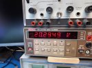
20250918_193720.jpg

The DMM at no power, measuring the dummyload

20250918_194533.jpg

the transformers

20250918_200442.jpg20250918_200515.jpg

Back of the bryston. This one has modules having green leds on the front, and a Bryston-built remote power on PCB, and jacks. This model is a 120 Volts model but having TWO primaries each transformer, so THIS model actually can be turned into a 230 Volts model.
There are also the very old models having very flat big EI transformers, there are ones with black transformers too, and the latest ones from 2007 had plastic transistors instead of TO3, at the same time the cooling outlets on the top were not on the front but on the back of the top plating. Mine has no mains power switch.
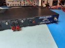
20250918_200150.jpg

BTW the very reason to take of the top plate was to really check that both amp channel power actually IS separate (read: each channel its own transformer and rectifier, NOT coupled together, which could have been a possibility)

Now, take notice of the power transistors. I think remembering Bryston also used MJ15022 and 15023 ones, or 024 and 025 in some models. Could these SJ partnumbers be exactly those well-known ones.....?


20250918_195922.jpg
 
Last edited:
The basics of performing measurements were given in post 31.

As far as the rest, it doesn't really matter what I do (but certainly I have the capability, and have done basic output power and power input draw measurements on amplifiers).

The non-deflected point here is what Bryston does, and that's design and build amplifiers (amongst other gear) that are well-regarded in the industry.

So, yeah, excuse my incredulity that a couple dudes on the Internet have unearthed some sort of dark secret about Bryston amps.

Yes, that has happened. Look at Bob Carver's Crimson 275 or whatever it was for a stellar example. It didn't take too terrible long for that to be sniffed out, not 38 years after the fact. The HUGE difference between that and this is the assertions of not meeting spec in the case of Carver Crimson 275 were backed by measurements showing it did not.

I think I must have touched some sort of nerve with the term undersized. They are undersized relative to how most other hifi amplifiers are built - even other amps from Bryston. The 3B and 4B which were contemporaries of my 2B-LP had 250VA and 500VA transformers respectively. In those, and most other hifi amps, the amp is designed not to exceed the capacity of the power supply for continuous operation at published specs.

If you prefer, let's just say that they are small.

Your suggested testing on post 31 is incorrect, or, at least, incomplete relative to this design.

In this design the expectation is that the output section can safely crowbar the power supply. I mentioned this before, but I wanted to clarify what I'm talking about. For comparison consider my PS Audio 200c. It has a single 1200VA transformer. It is specced at 200WPC@8, 400WPC@4, 800W into 2, and 1000W into 1.5. Originally it came with 3X 10A output transistors per rail. It can supply 1000W to one channel (not bridged) because there is only one transformer, so either channel can draw the full current the transformer can source. The PS Audio 200c also had a reputation for incendiary behavior. This is because, if the load became a short on one channel, the amount of current being pulled through those three transistors from one rail was more than they could survive even for the time it took for the output fuse to blow. Driving it hard into clipping could also also lead to transistors sticking to the rails and pulling against each other, again destroying the outputs because they could not shunt the full capacity of the transformer. So, in a nutshell, the 200c has 1200VA = about 8.5A of continuous current available into its 30A of continuous current output section, which sounds safe, but really isn't because the short term peak current from that transformer is much higher than 30A. The 2B-LP has probably 16A output devices, and has 100VA = about 1.7A continuous current from the one channel's transformer (because it is a dual-mono design). If we look at supply current to output current rating as a "crowbar factor", the 2B-LP is .106 and the PS Audio is .283. The Bryston is also common collector instead of an emitter follower, which likely gives it a benefit in the driver not exceeding output VBE when attempting to drive a short.

All of this is to say that, while your suggestion in post 31 is fine for testing whether the new transformers are sufficient in capacity and sufficiently close in voltage and regulation, it does not test what will happen if the amp is driven into a short. In most cases, replacing transformers with higher VA transformers when converting, repairing, or upgrading an amp, is fine. In this case, too big, or too efficient of transformers could actually be a problem. I have seen this amp exhibit its crowbar behavior when a friend of mine used it to drive a speaker that had a miswired XLR plug for its input. The amp actually got sound out of the speaker, while driving, bridged, in parallel with about 6mm of wire. It didn't sound good, and the amp got quite hot, but it didn't blow anything except the line fuses.

For my use, these new transformers will be fine. The fact that, at least in the later 2B-LP variants, Bryston said they were using 100VA devices, is reassuring. I do think, though, that the originals here are actually 80VA. The one question I have for Toroidy is how I should expect that their transformers behave if overloaded by 4X, which must have been part of Bryston's criteria in speccing their original parts.
 
Last edited:
Thanks for these tests.

Too bad you can't measure at other frequencies. I really wonder what distortion looks like near mains frequency when running at 100W into 4 Ohms. I will probably try this once I have mine all back together.

I don't understand why you would see more output voltage available at 8 Ohms with one channel driven when this is a dual-mono amp. The only possibility for one channel affecting the other in this way is if your supply is sagging.
 
Back
Top Bottom