• The move to the new server is done. There are some software and database maintenance updates in process. This has us passing the hat around to help out. We appreciate any donations. Seriously, even a dollar helps. The payment page may be found here - https://www.audiokarma.org/support.html

Build This Tube Amp With A Screwdriver

FlaCharlie

Super Member
So a few years ago I picked up a Switch Mode Power Supply (SMPS) that's designed for tube circuits. It has separate outputs for 6.3v and 12.6v heaters and a 300v output for the B+. But other projects took precedence so it sat on the shelf for a long time. Some folks over at DIYAudio had messed around with them with varying results. I culled as much info as I could from them and I finally got around to using it on my breadboard setup to power a basic SE circuit. The obvious attractions are low cost and simplicity.

This piqued my interest in extending that element of simplicity to the rest of the amp. I get the sense that there are a lot of folks who might be interested in building a DIY tube amp but are hesitant to take the plunge because they are overwhelmed by the complexity. My goal here is to present something that is far less intimidating for newbies.

This is a project that anyone CAN build. Not just a simple circuit but something that is extremely easy to assemble while still using point to point wiring.

So I've dubbed this one the Simplissimo. I'm not sure if that's a real word or not but I like it.

The result is a design whose construction requires no soldering. You can build this amp with a screwdriver and a few basic hand tools. It's nothing earth shattering. The same construction techniques are commonly used when breadboarding which is the experimental process I always use when I build a DIY project from scratch. It's a simple technique where all the parts are mounted to a wooden board. So no chassis fabrication skills are needed either.

My breadboard experiments always end up looking like a rat's nest with so many clip leads running everywhere that it's scary. So I've eliminated that aspect. And while my experiments typically do have some soldered connections, this just takes the next step and eliminates them. I plan on posting a few designs that use breadboard style construction and this SMPS.

Just to be clear, this build isn't so much about using a particular tube or circuit. I'm just using this SMPS as a turn-key power supply solution and combining it with simplified build techniques. Any design that can be powered with ~300v B+ can be built like this and it's easy to experiment since everything is wired point to point. Want to compare pentode, triode and UL? Try a boutique coupling cap? A different feedback resistor value? A different biasing method? A screwdriver is all you need.

Of course, if a more traditional build is preferred, the same construction techniques can be combined with a conventional power supply and some type of chassis. I'll be posting a different circuit later that combines these breadboard techniques with the same type of bamboo box that I used for a chassis with my Boogie Factor 1626 preamp. https://www.audiokarma.org/forums/index.php?threads/1626-preamp-build.931276/

Those who have read my previous build threads know that I like to keep costs low by using repurposed materials and I often use inexpensive, "under the radar", tubes. I've strayed from that formula just a bit here in that this design uses tubes that are common and in current production. I have not abandoned the low budget, bang for the buck, approach. You should be able to build it for ~$250 to $300.

I'm not a designer or an engineer. I'm just a hobbyist / copy and paste builder. I try to incorporate elements from other designs and combine them in different ways. There are many popular SE circuits out there which use a triode to drive a variety of output tubes. So you'll find many of the same elements I'm using here elsewhere. Truth is, there's not much new under the sun when it comes to tube amps.

For simplicity I decided to stick with octal tubes only and to save space I opted to use a single, dual triode, input tube. So I experimented with both the 6SN7 or 6SL7 as inputs in combination with numerous output tubes including the 6V6, EL34, 6L6GC, the Russian 6n3ce and the 7591. I tried running triode, pentode, UL and E-Linear, though not all combinations with every different tube. I also tried a variety of biasing methods for the input tube and some other circuit variations.

In the end I chose the EL34 which offers a good combination of power and affordability with a 6SL7 on the input. No, I haven't abandoned the use of oddball tubes and the versions that follow will likely use some.

Building the same circuits over and over again is not my style. I usually try to incorporate at least a few "new to me" elements in my DIY projects. Gotta keep it fresh and interesting.

Although I have some vintage PP EL34 amps that I've restored, I've never built anything from scratch with an EL34 or a 6SL7. I've also never built an Ultra Linear (UL) amp or anything that uses local, plate-to-plate (aka Schade), feedback. And, though I used SMPSs to heat the tubes in my most recent amp, the Cockeyed Monkey ( https://www.audiokarma.org/forums/i...ckeyed-monkey-a-directly-coupled-set.1040847/ ), the use of a SMPS to power everything is also new to me.

The output section is just a basic UL EL34 design using local, plate-to-plate (aka Schade), feedback. The current popularity of Schade FB is often traced to the RH amp designs but it's really nothing new. I recently came across a schematic for a "house brand" radio that was sold in Western Auto stores starting in 1947. It uses Schade FB in its amplifier section, which consists of a 6SQ7 driving a 6V6 output tube.

This basic output section is now very common. One example is the Skunkie Designs EL34 amp. @StepheK is now selling handcrafted, custom built amps using the same basic output section for ~$2000 to $2500, I believe. The most expensive version uses the legendary ISO Tango OTs! Of course she also has a series of step-by-step videos on her YouTube channel for those who want to build it themselves.

And Analog Ethos sells SE EL34 kits using the same UL output section design for ~$1300 to $1600. Their instructions are superb and this is a great option for those who would rather not deal with chassis fabrication. I've also seen some schematics that use the same circuit with different output tubes, such as the 6V6. So the basic design is well known and respected.

For the input I'm using the 6SL7, which is a dual triode. And just like the amps mentioned above, I'm using one triode to drive each EL34.

Besides the use of a SMPS and breadboard construction techniques there are two main differences between the designs mentioned and this one. The most obvious one is that this PS only puts out ~300v, so I'm running the outputs at lower voltage and higher current while the others run higher voltage and lower current.

The other is that I use a AA battery to bias the 6SL7. I've used the same battery grid bias scheme for input tubes in other builds too. It's simple to implement and I like how it sounds. Because the tube does not draw current from the battery, the battery will last as long as its shelf life. For a common Alkaline that should be at least 3 to 4 years. For a lithium it's probably 8 to 10 years. You must use regular batteries in this application. You can not use rechargeables.

Of course you can try other bias schemes. For example, Stephe uses a combination of a resistor and an LED to bias the dual triode 5751 input tube in her amp. The 5751 is a 9 pin miniature that has the same amplification factor (mu 70) as the 6SL7, BTW. The Analog Ethos kit uses the more traditional combination of a cathode resistor and bypass cap to bias a dual triode 12AT7, another 9 pin miniature.

I tried both of these alternatives and preferred the battery method but YMMV. I encourage prospective builders to take full advantage of the breadboard and point-to-point construction methods used here. Break out the screwdriver and experiment!

Anyway, here's a pic of the finished amp. Yeah, it's not much to look at:
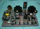
Finished Amp.jpg
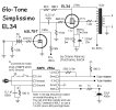
And here's the schematic:

Simplissimo EL34 Schematic.jpg
Since most people who can't solder or fabricate a chassis probably can't read and build from a schematic either, I'll add some (hopefully) easy to follow wiring diagrams, a few in-progress pics and some construction notes, along with a basic parts list later. Oh, and if you're concerned about using breadboard construction because of the high voltages that are present, that will be addressed too. I'll do my best to try to present all this in a newbie friendly manner.

Again, my goal here is to encourage people to get into the DIY aspect of this hobby we all enjoy.

If you're DIY curious I encourage you to check out the excellent Skunkie Designs videos as well as other build channels on YouTube, the kits available from Analog Ethos and others, as well as the many AK threads that focus on restoring and modding amps pulled from old console stereos. What I'm presenting here is just another "intro to DIY" option.
 
Register to hide this ad
No cold solder in that project! :D


There's plenty of soldered joints in that photo, you just didn't do the soldering.
You put your trust in some industrial process and they did it for you.
Nothing wrong with that.

Having no soldering iron just means that when you get a board with a failed joint, you get to send it back and hope for a better one, vs just fixing it yourself in minutes for pennies.
Same with soldered tube pins.
All in good fun.
Lean to solder kids! Learning things makes life easier and improves the life of those near you, deciding that you don't need to learn things means you're going to struggle more, due to the limits you have placed upon yourself.
 
Looks like a junior high science project, and hopefully it encourages someone who wants to make an amp. I built a 50L6/12SQ7 amplifier using very similar techniques (local electronics store had octal relay sockets but no solderable tube sockets) when I was around 13, and it was plenty of fun.
 
It wouldn't scare me. :biggrin: Just build it into a chassis instead of a breadboard.
I'm seeing these SMPS's used more and more in builds. Here and over at DIY. They save money, and they're lighter. Even companies like Crown are using them in there CDi series pro amps.
 
I'm seeing these SMPS's used more and more in builds.
My current preamp project uses a modified SMPS for the 6.3V filaments. And my 211 monos use the AC output (80 kHz) from an "electronic transformer" SMPS for the DHT filament. I realize these things won't survive as long as a simple transformer, but they have significant benefits. I don't care if someone else has to fix or replace them 30 years from now.
 
My current preamp project uses a modified SMPS for the 6.3V filaments. And my 211 monos use the AC output (80 kHz) from an "electronic transformer" SMPS for the DHT filament. I realize these things won't survive as long as a simple transformer, but they have significant benefits. I don't care if someone else has to fix or replace them 30 years from now.
They're cheap and easy enough to replace if needed years down the road.l too.
 
Curious about the SMPS. The schematic refers to a model ending in -U1 for 12.6V but I don't see the complete brand or model number.
 
They're cheap and easy enough to replace if needed years down the road.l too.
Maybe not. Mine are all customized. The 6.3 VDC had to be modified with different values around the adjustment pot to set that voltage. The 80 kHz version has major modifications. If it ever burns up and catches fire (a common failure mode for SMPS), the tech who tries to fix or replace it will be in trouble. I have documentation that will make the job easier, but it will still be time consuming and not inexpensive. The other thing is, who knows if any of these products will still be available as replacements when the time comes? It's all just very different than using a basic transformer, but there are pros and cons to everything. Here are the two I built using the "electronic transformer" SMPS:

211 filament PS 01 sm.JPG

Jack
 
Just build it into a chassis instead of a breadboard.

Its the exposed high voltage part of it that scares me. If thats not anywhere I can accidentally stick a finger into when its inside the house I'm fine with it. If I'm being honest even things like a Dynaco ST-70 make me kind of nervous when run without the cage. I don't have kids but I do have some pretty dumb moments of my own and I like to make some attempt at self-proofing things.
 
Its the exposed high voltage part of it that scares me. If thats not anywhere I can accidentally stick a finger into when its inside the house I'm fine with it. If I'm being honest even things like a Dynaco ST-70 make me kind of nervous when run without the cage. I don't have kids but I do have some pretty dumb moments of my own and I like to make some attempt at self-proofing things.
Couldn't agree more. This is why I don't build audio gear using tubes with top anode connections.
 
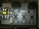
So here's a pic that shows the basic bits mounted to the board:

Basic Layout.jpg

The board itself is just particle board that's typically used for shelving. It's easier to screw into than solid wood. I use a drill to start the holes but if you don't have a drill a hammer and a nail should work fine too.

One reason I wanted to go with octal tubes is that the breadboard sockets for them are very inexpensive. If you shop around you can find them on eBay for ~$3 each shipped or about half that on Amazon for the parts themselves. They are used for electrical relays and are usually listed as octal relay sockets, not as tube sockets. Since they're quite common the price is low. Other types of tube sockets that are designed for breadboard / experimental use can also be found (7 and 9 pin miniature, octals, loctals, 4, 5, 6, 7 pins for use with older tubes, compactrons too) but they are typically at least 2x to 3x more expensive. These types are generally mounted on a small circuit board.

While I use a variety of connectors on my experimental breadboard, for a more finished build like this I prefer these barrier strips. Their screws are easy to access and, on these, the metal strip that connects each pair of screws can also be removed if necessary, which increases their versatility. These were from AliExpress but similar ones can be found elsewhere.

The SMPS I'm using is advertised as HiFi 250w Switch Power Supply DC300v 0.6A +12.6v@4A +6.3v@4A For Tube Amplifier PSU.

If anyone wants to delve into the technical aspects of this, or other SMPS, please start your own thread or go over to DIYAudio where there are numerous threads about SMPS in general and at least one thread about this particular unit. That's how I became aware of them.

I don't know anything at all about SMPS design and I don't claim to have a high level of expertise with these but I'll make a few comments based on my experiences.

They don't seem to be branded but they have a label on one side and there seem to be two model numbers being sold. The first one I bought was found on eBay some years ago. It has a number that ends in -52. More recently I picked some up on AliExpress, where they are a bit cheaper (under $40 shipped). Their model numbers end in -U1.

They (both versions) have a delay to the B+ (high voltage) startup. They claim that it starts 30 sec after the heater voltage but the delay on the ones I have is more like 10 or 12 sec, which seems to be plenty. There is a slight click when the B+ starts but it's not loud enough to be a concern.

One quirk I found with the -52 version was that it went into protection (hiccup) mode whenever I had anything connected to the 12.6v heater output. It would immediately shut down and then try to restart. That was disappointing because I was hoping to have the option of running 12SN7 or 12SL7 tubes since they're cheaper than 6SN7s and 6SL7s. I was also considering a 6V6 design that could also run 12V6s. It's possible that I had it hooked up wrong, I suppose. It's also possible that this issue has been fixed. As I said, I bought this -52 version years ago.

And it might eventually start. I say that because another user who experienced hiccup issues seemed to be content to just let it go through this cycle repeatedly because it would eventually start up. I'm not so patient. The -52 version works fine with only 6.3v tubes though. And there seem to be some other solutions which are discussed over in the DIY thread.

I suspect that the -U1 version may be an updated model because it works fine with any combination of 6.3v and 12.6v tubes. I did notice, however, that the B+ voltage at startup is more controlled if you have some type of load on the 12.6v output. I'm using a resistor but using a 12.6v tube or even a 12v pilot light works too. I have not tried to use only 12.6v tubes so I don't know if the 6.3v output should also be kept loaded in that situation.

Though not commonly used in tube amps, switch mode supplies are widely used in all sorts of applications. Everyone has equipment that runs off of external SMPS "wall warts" or internal supplies. Apparently they can, and usually do, generate noise at their switching frequency. I have no way to measure such things and I really only care about noise I can hear, unless it results in damage.

Perhaps the most interesting comment I've read on this was in a post by renowned designer Pete Millet over on DIY where he said, "most of the worry about noise when using switchers in audio is pure superstition. 60Hz rectifiers inject a lot more junk than a properly designed SMPS."

I have no idea if this particular supply is "properly designed" but, in practice, it seems to work well enough. I have a very large number of tube amps, both DIY and vintage, all of which use traditional power supplies. While this amp is not dead silent with ear to speaker it isn't any noisier than they tend to be. It's actually quieter than many of them.

I mounted the SMPS using a 1" L bracket (aka corner brace) with a nylon spacer so that the unit is suspended above the surface of the board. The metal shell of the SMPS acts as a heat sink so this allows air flow underneath. A couple of thinner nylon spacers are placed underneath to add support. The copper bit is an electrical ground lug. These parts are all available at Lowe's, Home Depot or your local hardware store.

The heat sink / metal shell does get hot just as a normal power transformer does. Of course the tubes get even hotter. While I was experimenting with it there was no air flow under it. It was just sitting on the board with a piece of non-slip shelf liner foam underneath it. It did not get hot enough to cause problems, even after running it continuously for 12 hours.

The SMPS has a voltage adjustment but it affects the high voltage and heater voltage outputs simultaneously. So I just adjust it to get the 6.3v heater voltage right and then use whatever B+ that provides. All the output voltages are DC and remain rock steady after startup. The metal shell is tied internally to the safety ground of the AC input and I'm isolating it from signal ground as is often done with a normal PS.

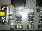
This pic shows a few parts mounted to the 6SL7 socket and the heater wiring.

Heater Wiring.jpg

I ran separate wires from the 6.3v output to the 6SL7 and the pair of EL34s. This allows me to switch to a 12SL7 by simply moving one wire over to the 12.6v output. I think I made some changes after I took this pic so you might notice some differences in pics I'll post later.

One suggestion I'd make is to install all the wires first and then go back and add the various parts. I didn't do that and it took me longer to build than it should have. Trying to run wires underneath other parts that have already been installed is kind of a pain. It's much easier if you do it in layers starting with the wires.

I'm using solid core wire instead of stranded wire as it's much easier to work with. Much of it is cloth covered "vintage style" wire from Antique Electronics and some is Military spec silver plated copper with teflon insulation, that I got from Apex Jr. Both of these suppliers sell it by the foot.

I'll post info on the connections later . . .
 
Last edited:
Its the exposed high voltage part of it that scares me. If thats not anywhere I can accidentally stick a finger into when its inside the house I'm fine with it. If I'm being honest even things like a Dynaco ST-70 make me kind of nervous when run without the cage. I don't have kids but I do have some pretty dumb moments of my own and I like to make some attempt at self-proofing things.
With my ST-70 I installed a plexiglass cover over the exposed high voltage bits. If a kid happens to touch a hot tube, we'll, that's just a learning experience. They won't do it again. :biggrin:
 

Attachments

  • 20231206_131525.jpg
    20231206_131525.jpg
    100.3 KB · Views: 53
So a few years ago I picked up a Switch Mode Power Supply (SMPS) that's designed for tube circuits. It has separate outputs for 6.3v and 12.6v heaters and a 300v output for the B+. But other projects took precedence so it sat on the shelf for a long time. Some folks over at DIYAudio had messed around with them with varying results. I culled as much info as I could from them and I finally got around to using it on my breadboard setup to power a basic SE circuit. The obvious attractions are low cost and simplicity.

This piqued my interest in extending that element of simplicity to the rest of the amp. I get the sense that there are a lot of folks who might be interested in building a DIY tube amp but are hesitant to take the plunge because they are overwhelmed by the complexity. My goal here is to present something that is far less intimidating for newbies.

This is a project that anyone CAN build. Not just a simple circuit but something that is extremely easy to assemble while still using point to point wiring.

So I've dubbed this one the Simplissimo. I'm not sure if that's a real word or not but I like it.

The result is a design whose construction requires no soldering. You can build this amp with a screwdriver and a few basic hand tools. It's nothing earth shattering. The same construction techniques are commonly used when breadboarding which is the experimental process I always use when I build a DIY project from scratch. It's a simple technique where all the parts are mounted to a wooden board. So no chassis fabrication skills are needed either.

My breadboard experiments always end up looking like a rat's nest with so many clip leads running everywhere that it's scary. So I've eliminated that aspect. And while my experiments typically do have some soldered connections, this just takes the next step and eliminates them. I plan on posting a few designs that use breadboard style construction and this SMPS.

Just to be clear, this build isn't so much about using a particular tube or circuit. I'm just using this SMPS as a turn-key power supply solution and combining it with simplified build techniques. Any design that can be powered with ~300v B+ can be built like this and it's easy to experiment since everything is wired point to point. Want to compare pentode, triode and UL? Try a boutique coupling cap? A different feedback resistor value? A different biasing method? A screwdriver is all you need.

Of course, if a more traditional build is preferred, the same construction techniques can be combined with a conventional power supply and some type of chassis. I'll be posting a different circuit later that combines these breadboard techniques with the same type of bamboo box that I used for a chassis with my Boogie Factor 1626 preamp. https://www.audiokarma.org/forums/index.php?threads/1626-preamp-build.931276/

Those who have read my previous build threads know that I like to keep costs low by using repurposed materials and I often use inexpensive, "under the radar", tubes. I've strayed from that formula just a bit here in that this design uses tubes that are common and in current production. I have not abandoned the low budget, bang for the buck, approach. You should be able to build it for ~$250 to $300.

I'm not a designer or an engineer. I'm just a hobbyist / copy and paste builder. I try to incorporate elements from other designs and combine them in different ways. There are many popular SE circuits out there which use a triode to drive a variety of output tubes. So you'll find many of the same elements I'm using here elsewhere. Truth is, there's not much new under the sun when it comes to tube amps.

For simplicity I decided to stick with octal tubes only and to save space I opted to use a single, dual triode, input tube. So I experimented with both the 6SN7 or 6SL7 as inputs in combination with numerous output tubes including the 6V6, EL34, 6L6GC, the Russian 6n3ce and the 7591. I tried running triode, pentode, UL and E-Linear, though not all combinations with every different tube. I also tried a variety of biasing methods for the input tube and some other circuit variations.

In the end I chose the EL34 which offers a good combination of power and affordability with a 6SL7 on the input. No, I haven't abandoned the use of oddball tubes and the versions that follow will likely use some.

Building the same circuits over and over again is not my style. I usually try to incorporate at least a few "new to me" elements in my DIY projects. Gotta keep it fresh and interesting.

Although I have some vintage PP EL34 amps that I've restored, I've never built anything from scratch with an EL34 or a 6SL7. I've also never built an Ultra Linear (UL) amp or anything that uses local, plate-to-plate (aka Schade), feedback. And, though I used SMPSs to heat the tubes in my most recent amp, the Cockeyed Monkey ( https://www.audiokarma.org/forums/i...ckeyed-monkey-a-directly-coupled-set.1040847/ ), the use of a SMPS to power everything is also new to me.

The output section is just a basic UL EL34 design using local, plate-to-plate (aka Schade), feedback. The current popularity of Schade FB is often traced to the RH amp designs but it's really nothing new. I recently came across a schematic for a "house brand" radio that was sold in Western Auto stores starting in 1947. It uses Schade FB in its amplifier section, which consists of a 6SQ7 driving a 6V6 output tube.

This basic output section is now very common. One example is the Skunkie Designs EL34 amp. @StepheK is now selling handcrafted, custom built amps using the same basic output section for ~$2000 to $2500, I believe. The most expensive version uses the legendary ISO Tango OTs! Of course she also has a series of step-by-step videos on her YouTube channel for those who want to build it themselves.

And Analog Ethos sells SE EL34 kits using the same UL output section design for ~$1300 to $1600. Their instructions are superb and this is a great option for those who would rather not deal with chassis fabrication. I've also seen some schematics that use the same circuit with different output tubes, such as the 6V6. So the basic design is well known and respected.

For the input I'm using the 6SL7, which is a dual triode. And just like the amps mentioned above, I'm using one triode to drive each EL34.

Besides the use of a SMPS and breadboard construction techniques there are two main differences between the designs mentioned and this one. The most obvious one is that this PS only puts out ~300v, so I'm running the outputs at lower voltage and higher current while the others run higher voltage and lower current.

The other is that I use a AA battery to bias the 6SL7. I've used the same battery grid bias scheme for input tubes in other builds too. It's simple to implement and I like how it sounds. Because the tube does not draw current from the battery, the battery will last as long as its shelf life. For a common Alkaline that should be at least 3 to 4 years. For a lithium it's probably 8 to 10 years. You must use regular batteries in this application. You can not use rechargeables.

Of course you can try other bias schemes. For example, Stephe uses a combination of a resistor and an LED to bias the dual triode 5751 input tube in her amp. The 5751 is a 9 pin miniature that has the same amplification factor (mu 70) as the 6SL7, BTW. The Analog Ethos kit uses the more traditional combination of a cathode resistor and bypass cap to bias a dual triode 12AT7, another 9 pin miniature.

I tried both of these alternatives and preferred the battery method but YMMV. I encourage prospective builders to take full advantage of the breadboard and point-to-point construction methods used here. Break out the screwdriver and experiment!

Anyway, here's a pic of the finished amp. Yeah, it's not much to look at:

View attachment 3225403
And here's the schematic:

View attachment 3225404
Since most people who can't solder or fabricate a chassis probably can't read and build from a schematic either, I'll add some (hopefully) easy to follow wiring diagrams, a few in-progress pics and some construction notes, along with a basic parts list later. Oh, and if you're concerned about using breadboard construction because of the high voltages that are present, that will be addressed too. I'll do my best to try to present all this in a newbie friendly manner.

Again, my goal here is to encourage people to get into the DIY aspect of this hobby we all enjoy.

If you're DIY curious I encourage you to check out the excellent Skunkie Designs videos as well as other build channels on YouTube, the kits available from Analog Ethos and others, as well as the many AK threads that focus on restoring and modding amps pulled from old console stereos. What I'm presenting here is just another "intro to DIY" option.

I think this is great. I buuilt a tone of stuff on breadboards just like that when I started DIYing.
 
As some comments have mentioned, one of the concerns about building on a breadboard is that there are high voltages present. Of course the most popular tube amp ever made, the Dynaco ST-70 uses an exposed circuit board and, from what I've seen, not many owners seem concerned.

Still I would encourage prospective builders to use a cage.

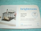
So where can you find a suitable cage? I often find metal mesh baskets at thrift stores for a few dollars and I've collected several of them on the odd chance that they can be repurposed. But, for this project, I wanted to be able to suggest something that can be more reliably sourced. I found the solution at Target although, at $20, it's more costly than I'd like. It's a metal mesh slide out storage drawer. Something similar can likely be found elsewhere.

Drawer.jpg

If you're planning on using a cage you really want to buy the cage first and then use it to determine the dimensions of your breadboard. That's what I did here. The actual size of the board I'm using is 8.5" x 13.75". I normally like to have a bit more space. I made it work but, as you can see, everything is pretty tightly spaced.

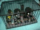
I opted to simply flip the drawer section over and set it over the amp as seen in this pic:

Cage.jpg

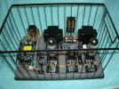
Another option would be to either place or secure the breadboard inside the drawer and access the amp by pulling the drawer open.

Amp in Drawer.jpg

If you want to use that method you will need to be sure that there is enough clearance for the speaker / input connections so the drawer can slide in and out. They stick out too much in the one I built so I would need to reposition them in order to use the in-drawer option.

In either case, those connections should not be allowed to come in contact with the vertical metal bars. The bars on this cage are spaced so that an IEC plug fits neatly between them if you position the connector correctly. You'll notice that the speaker / RCA jacks have a bar going right between them. So you need to cover that section of the bar with some type of insulation. I haven't added that yet but I'll probably use heat shrink or maybe just electrical tape.
 
As some comments have mentioned, one of the concerns about building on a breadboard is that there are high voltages present. Of course the most popular tube amp ever made, the Dynaco ST-70 uses an exposed circuit board and, from what I've seen, not many owners seem concerned.

Still I would encourage prospective builders to use a cage.

So where can you find a suitable cage? I often find metal mesh baskets at thrift stores for a few dollars and I've collected several of them on the odd chance that they can be repurposed. But, for this project, I wanted to be able to suggest something that can be more reliably sourced. I found the solution at Target although, at $20, it's more costly than I'd like. It's a metal mesh slide out storage drawer. Something similar can likely be found elsewhere.

View attachment 3226797

If you're planning on using a cage you really want to buy the cage first and then use it to determine the dimensions of your breadboard. That's what I did here. The actual size of the board I'm using is 8.5" x 13.75". I normally like to have a bit more space. I made it work but, as you can see, everything is pretty tightly spaced.

I opted to simply flip the drawer section over and set it over the amp as seen in this pic:

View attachment 3226809

Another option would be to either place or secure the breadboard inside the drawer and access the amp by pulling the drawer open.

View attachment 3226815

If you want to use that method you will need to be sure that there is enough clearance for the speaker / input connections so the drawer can slide in and out. They stick out too much in the one I built so I would need to reposition them in order to use the in-drawer option.

In either case, those connections should not be allowed to come in contact with the vertical metal bars. The bars on this cage are spaced so that an IEC plug fits neatly between them if you position the connector correctly. You'll notice that the speaker / RCA jacks have a bar going right between them. So you need to cover that section of the bar with some type of insulation. I haven't added that yet but I'll probably use heat shrink or maybe just electrical tape.
You can use a small strap, screws, and nuts to secure the top of the jack plate.
 
You can use a small strap, screws, and nuts to secure the top of the jack plate.
Good idea. For now I've just been holding the top to provide support while I plug or unplug.

I thought about spacing the OTs further apart which would have given me enough room to mount it horizontally with both ends supported. But I wanted a symmetrical layout with the output tubes directly in front of each OT and that would not have been possible unless I was able to use a larger board. But using a larger board would require a larger cage . . .

So mounting it vertically was just one of those design tradeoffs that are part of every DIY build. A totally different layout could be used, of course. I'm sure some prospective builders are more creative than I am.
 
Back
Top Bottom