FlaCharlie
Super Member
So for those who can't read schematics, I'll try to explain all the connections using the following wiring diagrams. While they're not step-by-step instructions like you'd find in a kit, they should be fairly easy to follow.
Here's the wiring diagram for the 6SL7 input tube which plugs into the center socket:
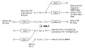
The connections close to the center of the diagram are numbered. They're the screws on the octal socket that go to the tube pins. You can see the orientation of the locator pin / keyway. The locator pin prevents the tube from being inserted the wrong way. Notice that, unlike the diagrams found in tube data sheets, the sequence here is counter-clockwise since we're looking at the top of the socket. The sockets have numbers molded into the plastic but they're tiny and difficult to see.
The connections further from the center are on the terminal strips. For simplicity, only one connection ( O ) is shown but each one actually represents a pair and connections can be made to either one of the pair since they are connected to each other.
Note that parts from Pins 4 and 5 of the 6SL7 go to 3 connections. Those 3 are on the larger 8 position terminal strip that's located in the center / on the rear side of the amp. I'll post a diagram of the entire 8 position strip later. Obviously, there will be some redundancy as some connections will appear on two different diagrams.
The parts / connections on Pins 1 and 2 of the 6SL7 go to a smaller terminal strip which only has 3 terminals. That strip is located in the center / on the front side of the amp.
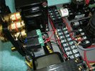
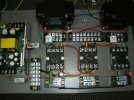
Here's an in-progress pic that shows some of that. I meant to take more of them but once I started wiring things up I got on a roll and didn't take many pics.
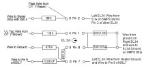
Here's the wiring diagram for the Left Channel EL34. The connections on the right side are on the 3 position barrier strip mounted on the front side of the amp. The connections on the left side are on the 4 position barrier strip mounted towards the rear of the amp.
Here's an in-progress pic of that:
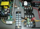
Similarly, here's the wiring diagram for the Right Channel EL34. Again, the connections on the right side are on the 3 position barrier strip mounted on the front side of the amp and the connections on the left side are on the 4 position barrier strip mounted towards the rear of the amp.
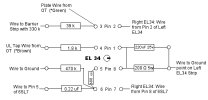
Note that Pin 8 (the cathode) and Pin 1 (G3) must be connected at the socket with a wire. Some tubes make this connection internally but the EL34 does not so the jumper wire is necessary. Also, the EL34 does not have a Pin 6. So I'm using that connection (Pin 6) on the socket as a tie point. This makes it easier to mount the grid stopper resistor since the resistor body should be mounted as close to the grid pin as possible. The grid stopper is the dark brown resistor in the pic. Pin 5 is the grid pin.
Here's an in-progress pic of the 6SL7 and the Right EL34:
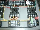
Here's the wiring diagram for the SMPS terminal strip, which has 6 positions:
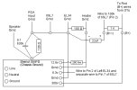
And here's a pic of it wired up:
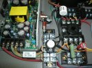
The SMPS terminal strip is mounted with nylon spacers so there's a gap between the bottom of the terminal strip and the board. This allows the green wires in the pic, which are the 6.3v heater wires, to run underneath the terminal strip on their way to the tube sockets. The orange wire, which is the heater ground, connects to the SMPS terminal strip as shown in the diagram.
Here's the wiring diagram for the 8 position terminal strip, which is mounted in the center / rear of the amp. Again, some of these connections are also described on other diagrams.

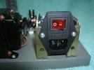
Here's a pic of the amp from the rear showing how I've mounted the IEC socket that connects the SMPS to the AC supply coming from the wall. I've used a combination IEC connector / fuse / switch and mounted it with a pair of 2" L brackets.
Looks like I've reached the 10 pic limit for posting pics in a single post so I'll continue in another post . . .
Here's the wiring diagram for the 6SL7 input tube which plugs into the center socket:
The connections close to the center of the diagram are numbered. They're the screws on the octal socket that go to the tube pins. You can see the orientation of the locator pin / keyway. The locator pin prevents the tube from being inserted the wrong way. Notice that, unlike the diagrams found in tube data sheets, the sequence here is counter-clockwise since we're looking at the top of the socket. The sockets have numbers molded into the plastic but they're tiny and difficult to see.
The connections further from the center are on the terminal strips. For simplicity, only one connection ( O ) is shown but each one actually represents a pair and connections can be made to either one of the pair since they are connected to each other.
Note that parts from Pins 4 and 5 of the 6SL7 go to 3 connections. Those 3 are on the larger 8 position terminal strip that's located in the center / on the rear side of the amp. I'll post a diagram of the entire 8 position strip later. Obviously, there will be some redundancy as some connections will appear on two different diagrams.
The parts / connections on Pins 1 and 2 of the 6SL7 go to a smaller terminal strip which only has 3 terminals. That strip is located in the center / on the front side of the amp.
Here's an in-progress pic that shows some of that. I meant to take more of them but once I started wiring things up I got on a roll and didn't take many pics.
Here's the wiring diagram for the Left Channel EL34. The connections on the right side are on the 3 position barrier strip mounted on the front side of the amp. The connections on the left side are on the 4 position barrier strip mounted towards the rear of the amp.
Here's an in-progress pic of that:
Similarly, here's the wiring diagram for the Right Channel EL34. Again, the connections on the right side are on the 3 position barrier strip mounted on the front side of the amp and the connections on the left side are on the 4 position barrier strip mounted towards the rear of the amp.
Note that Pin 8 (the cathode) and Pin 1 (G3) must be connected at the socket with a wire. Some tubes make this connection internally but the EL34 does not so the jumper wire is necessary. Also, the EL34 does not have a Pin 6. So I'm using that connection (Pin 6) on the socket as a tie point. This makes it easier to mount the grid stopper resistor since the resistor body should be mounted as close to the grid pin as possible. The grid stopper is the dark brown resistor in the pic. Pin 5 is the grid pin.
Here's an in-progress pic of the 6SL7 and the Right EL34:
Here's the wiring diagram for the SMPS terminal strip, which has 6 positions:
And here's a pic of it wired up:
The SMPS terminal strip is mounted with nylon spacers so there's a gap between the bottom of the terminal strip and the board. This allows the green wires in the pic, which are the 6.3v heater wires, to run underneath the terminal strip on their way to the tube sockets. The orange wire, which is the heater ground, connects to the SMPS terminal strip as shown in the diagram.
Here's the wiring diagram for the 8 position terminal strip, which is mounted in the center / rear of the amp. Again, some of these connections are also described on other diagrams.
Here's a pic of the amp from the rear showing how I've mounted the IEC socket that connects the SMPS to the AC supply coming from the wall. I've used a combination IEC connector / fuse / switch and mounted it with a pair of 2" L brackets.
Looks like I've reached the 10 pic limit for posting pics in a single post so I'll continue in another post . . .