• The move to the new server is done. There are some software and database maintenance updates in process. This has us passing the hat around to help out. We appreciate any donations. Seriously, even a dollar helps. The payment page may be found here - https://www.audiokarma.org/support.html

But what about Grommes?

Carbsandcaps

Super Member
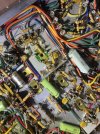
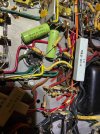
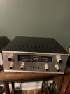
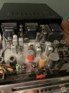
Picked up this grommes 502c multiplex receiver today. It’s got a nice gold colored faceplate, nice this case and some very clean wiring underneath including Cornell doubler capacitors. It certainly has a pilot look to it. It uses 6eu7’s and el84’s and ported outputs. It sounds decent but has a noticeable hum so I’m sure it needs some capacitors.

But anyway I don’t see much about grommes. I see they are still in business which is always a good thing. Does anyone have any experience with their receivers? IMG_2661.jpegIMG_2662.jpegIMG_2650.jpegIMG_2651.jpeg
 
Register to hide this ad
Grommes made some very decent stuff, but it's true that you don't see much of it anymore. Thirty years ago tube buffs turned their noses up at it because it wasn't Marantz or Harman-Kardon, and it looked pretty industrial. They also, believe it or not, turned their noses up at Eico gear.
 
Grommes made some very decent stuff, but it's true that you don't see much of it anymore. Thirty years ago tube buffs turned their noses up at it because it wasn't Marantz or Harman-Kardon, and it looked pretty industrial. They also, believe it or not, turned their noses up at Eico gear.

I agree. The more I look at this, the more quality I see. The way they angled the wiring, even the way they bent the leads to the diodes uniformly. That’s the stuff that you don’t have to do assuming nobody would ever see it but it shows pride in your work. I’m going to convert the 6eu7’s to 12ax7’s to give more preamp options and see how it sounds. Pretty excited about this one.
 

Attachments

  • IMG_2667.jpeg
    IMG_2667.jpeg
    203.9 KB · Views: 39
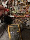
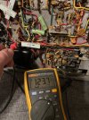
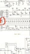
But now I’m trying to figure it out without a wiring diagram. It’s got 2 wires coming out of the transformer that I can’t figure out. One goes directly to the cathodes then to a 100ohm resistor to ground which I’m assuming is the center tap of the hv line and has 12vdc on it. The other got straight to a 40uf capacitor then to the selector switch. This wire has 123vdc and 58vac on it. I really need to find a diagram IMG_2668.jpegIMG_2674.jpegIMG_2673.jpegIMG_2668.jpeg
 

Attachments

  • IMG_2672.jpeg
    IMG_2672.jpeg
    184.6 KB · Views: 9

has a schematic for a 502M. Might be close enough to guide you.


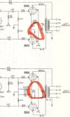
looks like the 100 ohm is the output tube cathode bias resistor. The connection to the power transformer is center tap on the 6.3 vac heater winding. This will elevate the heaters by about a dozen volts DC thanks to the cathode voltage.
 

has a schematic for a 502M. Might be close enough to guide you.


looks like the 100 ohm is the output tube cathode bias resistor. The connection to the power transformer is center tap on the 6.3 vac heater winding. This will elevate the heaters by about a dozen volts DC thanks to the cathode voltage.

Yes perfect, thank you! Looks like the center tap of the hv secondary goes straight to the cathodes of the the outputs. The other wire that I can’t figure out goes to the ground do the am or fm sections of after the selector switch. Pretty interesting design. Thanks again!
 
The Burstein Applebee version uses much smaller output transformers. Not a surprise, I can't recall any equipment they sold back in the day that I thought was good quality. Well below the standards even of companies like Olson and Lafayette.

Jack
 
Yes perfect, thank you! Looks like the center tap of the hv secondary goes straight to the cathodes of the the outputs. The other wire that I can’t figure out goes to the ground do the am or fm sections of after the selector switch. Pretty interesting design. Thanks again!
thats not the high voltage secondary center tap, its the 6 volt heater winding center tap.

If this uses a bridge rectifier arrangement like the schematic and the 4 diodes in your pic imply, the HV center tap does not go to ground. Its used as the low voltage take-off point for the tuner plate supply. Bridge rectifiers don't ground the center tap. Most of them don't even use a center tap.
 
thats not the high voltage secondary center tap, its the 6 volt heater winding center tap.

If this uses a bridge rectifier arrangement like the schematic and the 4 diodes in your pic imply, the HV center tap does not go to ground. Its used as the low voltage take-off point for the tuner plate supply. Bridge rectifiers don't ground the center tap. Most of them don't even use a center tap.

So what does the center tap of the 6v supply do
 
If this uses a bridge rectifier arrangement like the schematic and the 4 diodes in your pic imply, the HV center tap does not go to ground. Its used as the low voltage take-off point for the tuner plate supply.
That used to be known as an "economy supply." The center tap produces roughly one-half the voltage of the main output of the bridge. This was fairly common at one time in tube-type communications equipment for powering output tube screens. It's particularly well-suited to tubes like the 6146 and 807 that impose screen voltage limitations that are well below the voltage applied to the plate.

Jack
 
Grommes (pron: Grow-mez) is still owned and run by the ancestors of Bill Grommes in the Chicago area, under the name Grommes Precision. They make commercial and industrial audio PA equipment and about 15 years ago they had briefly considered re-entering the tube audio business and built several prototypes. It's still listed as Grommes Hi-Fi on the website but as far as I know it never materialized. I was writing and editing articles for Vacuum Tube Valley Magazine at that time and interviewed their chief Engineer regarding their prototype amplifier and subsequently wrote and submitted an article on the history of Grommes (and also on Stromberg-Carlson) that were never published due to the death of the publisher and the end of the magazine. In any event Grommes made excellent products for the home audio consumer for many years starting in the early 1950s and into the early SS era, and still continues in the audio products business under the auspices of the original family. This should be an excellent performing receiver with proper restoration, well worth the effort.
 
That used to be known as an "economy supply." The center tap produces roughly one-half the voltage of the main output of the bridge. This was fairly common at one time in tube-type communications equipment for powering output tube screens. It's particularly well-suited to tubes like the 6146 and 807 that impose screen voltage limitations that are well below the voltage applied to the plate.

Jack

So the center tap is at the 6.3v heater string winding and then goes right to the cathodes so how does it get rectified to 12vdc? Its not a huge deal because the voltages are correct I’m just trying to learn something. IMG_2677.jpegIMG_2678.jpeg
 
Its not supplying anything. The 12 volts DC is the current flow through the 6bq5 output tubes. The 6v heater supply is tied to that for a ground reference, and to elevate the heater supply above ground to reduce noise. You could move that connection to ground and it would all still work, though it might pick up some extra hum.
 
Its not supplying anything. The 12 volts DC is the current flow through the 6bq5 output tubes. The 6v heater supply is tied to that for a ground reference, and to elevate the heater supply above ground to reduce noise. You could move that connection to ground and it would all still work, though it might pick up some extra hum.

Ok so it’s getting its ground through the 100ohm resistor.
 
So what does the center tap of the 6v supply do
That was used to ground the filament supply symmetrically. Hum from filament AC voltage could be reduced better this way than by grounding one or the other end of the filament winding. It's possible that some equipment placed a DC bias on that center-tap for the same reason.
 
Back
Top Bottom