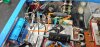
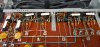
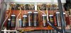
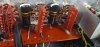
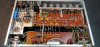
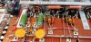
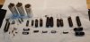
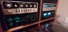
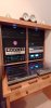
I recently acquired what appears to be an original C11. It has the silicon rectifier bridge (either the mod per service bulletin 105 or factory) but retained the original selenium rectifiers for the B+. Unit appears to have been produced in second half of 1962 (based on various component date codes). The unit was in working condition when received, although one channel was intermittent and had lower output. Unit has 6 original Telefunken smooth plate 12AX7, the 12 triode sections test between 66% and 90% of the bogey on my Hickok 800A, no shorts, no gas.
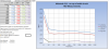
Before doing any work, I took voltage readings per the factory service manual - more on this below. I also checked for DC at the outputs, there was none, and scoped the outputs. Using the side output levelers, I was able to balance the output voltage, but one channel looked terrible with a square wave. I then cleaned all the pots, switches, and tube sockets with a sequence that included CRC QD Contact Cleaner, Deoxit5, and F5 fader lube for pots. Cleaning was done with faceplate and glass removed to ensure these pretties did not get damaged from spray. The cleaning worked wonders - see before/after scope photo.
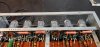
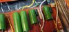
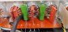
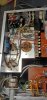
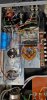
Now I was ready to start the recap - focusing on the power supply, I installed three new can caps (CE 50/50/50/50 @350v, CE 40/20/20/20 525v, and Authenticap 2000/2000 @35v) + discrete caps for C104 (47 @350v) and C102A (1000 @40v). The "kit" I used also included a 20v Zener, and 1N4007s to replace the selenium rectifiers, and two 1N5408 to adjust heater voltage. I did not initially install the 1N5408s. I also replaced power supply resistors R101 through R106 with new 1/2W metal film resistors, since I was in there.
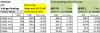
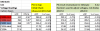
After the cap install, I checked voltages at 117 and 122 vAC. See voltage chart.
With the Zener installed between C104 and R102, the voltages were between 8% and 11% below spec at 117v (very close to the pre-recap values) except for the heater voltage, which was a about 7% high (higher than before the recap). I then removed the Zener from the circuit (returning to stock except for 1N4007s), this brought the B+ voltages up to within 3%- 6% below factory at 117v, not bad, but the heaters were still above 20v, vs. spec of 18.9. To see if I could get the heater voltage down I put the two 1N5408s in series between C101A (1000 uF) and the heaters (connection to the string is at V6). This brought the heater voltage down about 1v to 19.06, which is less than 1% above spec. I then increased the line voltage to 122.1 to see what voltages look like with my normal line voltage, this pushed the B+ voltages to within +/- 2.5% of spec, and the heater voltage went up a full volt to 20.15v.
The voltage directly out of the bridge is also higher than spec, it is running about 30v vs. 27.6, could I bring this down with a resistor? I can run this through a decade resistor box to get the right resistance rating, would a 1W do, or should I go with a higher wattage. Bringing this voltage down may give me the heater voltages I am looking for without the need for the 1N5048s.
With all these permutations, I am trying to figure out the "best" compromise, and also, why with new caps and resistors, can't I "match" the original voltage specs?
If a resistor after the bridge does not bring the heater voltage down, I will likely go with the 1N5408s in series, but I am waffling between lower B+ voltages with the Zener in place, and closer to spec, but still slightly low @117, voltages without the Zener.
So the question is would you keep the Zener? What is the downside to running low vs. slightly high B+ voltages?
Thanks for your input - Gary
Before doing any work, I took voltage readings per the factory service manual - more on this below. I also checked for DC at the outputs, there was none, and scoped the outputs. Using the side output levelers, I was able to balance the output voltage, but one channel looked terrible with a square wave. I then cleaned all the pots, switches, and tube sockets with a sequence that included CRC QD Contact Cleaner, Deoxit5, and F5 fader lube for pots. Cleaning was done with faceplate and glass removed to ensure these pretties did not get damaged from spray. The cleaning worked wonders - see before/after scope photo.
Now I was ready to start the recap - focusing on the power supply, I installed three new can caps (CE 50/50/50/50 @350v, CE 40/20/20/20 525v, and Authenticap 2000/2000 @35v) + discrete caps for C104 (47 @350v) and C102A (1000 @40v). The "kit" I used also included a 20v Zener, and 1N4007s to replace the selenium rectifiers, and two 1N5408 to adjust heater voltage. I did not initially install the 1N5408s. I also replaced power supply resistors R101 through R106 with new 1/2W metal film resistors, since I was in there.
After the cap install, I checked voltages at 117 and 122 vAC. See voltage chart.
With the Zener installed between C104 and R102, the voltages were between 8% and 11% below spec at 117v (very close to the pre-recap values) except for the heater voltage, which was a about 7% high (higher than before the recap). I then removed the Zener from the circuit (returning to stock except for 1N4007s), this brought the B+ voltages up to within 3%- 6% below factory at 117v, not bad, but the heaters were still above 20v, vs. spec of 18.9. To see if I could get the heater voltage down I put the two 1N5408s in series between C101A (1000 uF) and the heaters (connection to the string is at V6). This brought the heater voltage down about 1v to 19.06, which is less than 1% above spec. I then increased the line voltage to 122.1 to see what voltages look like with my normal line voltage, this pushed the B+ voltages to within +/- 2.5% of spec, and the heater voltage went up a full volt to 20.15v.
The voltage directly out of the bridge is also higher than spec, it is running about 30v vs. 27.6, could I bring this down with a resistor? I can run this through a decade resistor box to get the right resistance rating, would a 1W do, or should I go with a higher wattage. Bringing this voltage down may give me the heater voltages I am looking for without the need for the 1N5048s.
With all these permutations, I am trying to figure out the "best" compromise, and also, why with new caps and resistors, can't I "match" the original voltage specs?
If a resistor after the bridge does not bring the heater voltage down, I will likely go with the 1N5408s in series, but I am waffling between lower B+ voltages with the Zener in place, and closer to spec, but still slightly low @117, voltages without the Zener.
So the question is would you keep the Zener? What is the downside to running low vs. slightly high B+ voltages?
Thanks for your input - Gary
Attachments


Last edited: