• The move to the new server is done. There are some software and database maintenance updates in process. This has us passing the hat around to help out. We appreciate any donations. Seriously, even a dollar helps. The payment page may be found here - https://www.audiokarma.org/support.html

C32 restoration

IvoCRO

Active Member
Well, things are getting started. Listening time is over as all parts has arrived for C32 and now it is time to disassemble it. I will post here my progress as time will allow since holidays are around and "...are you telling me that we will again have parts all over living room for weeks...". I will try to take a pictures and document as much as I can.

First thing that I would like to fix are bubbles on front glass. Here is a picture:

glass1.JPG

As I remember, c_dk sad in one of his posts that he managed to fix this. So, before I attempt to do anything, I would like to hear all suggestions of what to do and what to avoid in fixing bubble problems.

Thanks all,

Ivo
 
Register to hide this ad
I am considering some safety issues with suppression capacitors in mains section over the line to ground. Here is simplified picture:

mains.JPG

Upper schematics is simplified original drawing where capacitors are connected to ground (which is chassis) from live and neutral wires. If any capacitor fail shorted and if it is on live side then whole chassis will be on live potential and lethal to touch, especially if mains is 220 V.

Since these capacitors were introduced, I was thinking of applying lower schematic. Capacitors are still present, and they still function as suppressors. But they are grouded on ground on third prong of wall electrical outlet, not on the chassis. So, if any of them fail short and is on live wire, chasiss will not be on live potential and fuse will break.

In Europe, most of wall electrical outlets and household electrical circuit has Live (brown), Neutral (blue) and Ground (yellow/green).

What do you think of using lower schematic for suppression capacitors?

In any case, on both drawings capacitors should be Y or X / Y class.
 
"...are you telling me that we will again have parts all over living room for weeks..."

Lol, in my case the parts are all over the kitchen for weeks. :cool: and the sink come in handy!

..and there were speakers leaning backward on the sofa (45º) with the drivers removed. :thumbsup:
 
"...Come with me
Into the trees..."

The one who knows which song begins with that words knows that song's title is the title of this post.

Or I can say that things began to unfold...

nothing_inside.jpg
 
"...Come with me Into the trees..." The one who knows which song begins with that words knows that song's title is the title of this post.

That's a strange parallel for dismantling [stripping] your chassis. It's easy to find what song those lyrics are from:

And that expression is pagan at best, and likely satanic. Do another search for:

Everyone has heard of Bohemian Grove and the recent Comet Pizza joint in Washington.

See anything strange in the following Google Earth street view?

Comet_562_495x.jpg Comet_570_600x.jpg


That being said, keep us posted on your C32 progress.
-
 
Last edited:
Before removing flat cables from their connectors, I put some tape arround their ends and this helped to keep cables not to fall apart:

tape.jpg

You can notice piece of tape in the middle of cable where it begins to separate. Is this what you call mask tape?

First board was Record switch board. It has only 3 capacitors to change, but I also wanted to look at the contacts of rotary switch. I know that audio signal is not going through rotary contacts, but I wanted to check it anyway as switch is about 40 years old.

So, here is board before:

before.jpg

Board in progress:

inbetween.jpg

Board after:

after.jpg

And here is picture of switch from underside. You can see that used part of switch is only half of metal circle:

sw1.jpg

I decided to clean only half of metal circle to minimise little tiny hairs (don't know how to describe better) that cotton swab may leave while cleaning. Lightning may not show, but metal circle is well cleaned and polished:

sw2.JPG

How do you clean metal contacts? As you see, I use cotton swabs and polish paste.

Parts thet were used, all Nichicon:

10uF/16V -> 10uF/16V, VR series, 3X

To be continued...
 
Masking tape is also known as painters tape, used when painting to protect adjoining surfaces. It looks like you used a clear tape known here in the states as "Scotch" tape named by the 3M company back in the 50s. It is a polyethylene adhesive backed tape. The important thing is that the adhesive does not ooze or get slimy over time.

The loose faceplate paint can be "flicked" off. The key is to use a motion to carefully almost slide a blade, that is little scrapes, away from the well bonded paint without scratching the glass or loosening more paint. The edge doest not need to be smooth, just so the remaining paint is still bonded. If the bubble is close to the lettering you will most likely fail. You can buy new glass.

The Rustoleum brand of black enamel has usually been a good match, except for the last MC2155 amp I needed to touch up. Ended up using a BMW black touch up paint to get the correct shade of black.

Trying to use words the universal translator will translate correctly is more difficult than I thought it would be.

Lastly, a pencil eraser works best to clean those types of surfaces followed by some Caig D5 DeOxit.
 
View attachment 838016

How do you clean metal contacts? As you see, I use cotton swabs and polish paste.

Parts that were used, all Nichicon: 10uF/16V -> 10uF/16V, VR series, 3X

There ought to be a chemical solution (pun intended) for the rotary switch plates and contacts. There's a trick for instantly cleaning the brass prongs of a AC power plug. I dipped the prongs in a shot-glass of CLR and swished for a few seconds, even though it says DO NOT USE ON BRASS, then quickly rinsed in [another glass of] water. It was an instant brass cleaner.

-Gregory
 
Thanks for advice, but I don't have any kind of liquid chemical for cleaning, so I carefully use cotton swab:) There is a cleaning spray on the market and I use it when I can't access moving parts of switches.

And as I talk about switches, here is another finished board, and this time winner was Listen/Mode board:

before2.JPG

Here is Mode switch, before:

sw1.JPG

and after cleaning:

sw2.JPG

And here is Listen switch, again only half of rotary circle is used and half is only cleaned. Before:

sw3.JPG

and after cleaning:

sw4.JPG

Little board is waiting to be reassembled again:

working.JPG

One thing that I have noticed on this board - copper traces and soldering job was very poor on this board. Some solder places still had small portion of green protective film across, so solder was not evenly spread on soldering point.

On this board there was no parts to change.

I almost forgot, this is the tape that I am using, and indeed painter use it for protection while painting (usually walls). And it tears almost like paper:

masktape.JPG

Well, this is it for today, it is almost half past midnight on my side of planet, so good night everybody........or good afternoon:)

Ivo
 
As I mentioned before, frequency of my posts is a bit slow as holidays are here and I must obey on what my wife tells me since I occupied half of living room with you know what.....

I have changed main filters capacitors. I have read that filter capacitors are not 'must change' and that they rarely fail, but I decided to change them since they are about 40 years old and was not very expensive, about 10 Eur for one. I have also checked capacity of old and new ones and here is the difference. I know that this kind of measurement is not truly realistic, but it gives rough picture. Capacity is 4700 uF.

Old one, both of them had same capacity:

Resize of old.jpg

New one:

Resize of new.jpg

And here they are nicely fitted:

Resize of new_home.jpg

One thing about new capacitors - usually marking on capacitor body is on negative pole, but on these capacitors marking is on positive pole.

Tomorrow I have a family for dinner and I am not sure that I will have time for more work and to visit forum, so under my tree are all best wishes to all of you and your families for holidays and Christmas.

tree.jpg

Ivo
 
Ivo

Overall the inside of your C32 looks pretty clean.

For the bubbling on my C26 I cut around it w a sharp razor and applied several thick coats of black enamel ...Rust-O-Leum. Worked out well
 
"Empty spaces - what are we living for
Abandoned places - I guess we know the score..."
- this song should carry the title of this post!
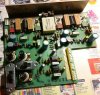
It has been a while since my last post. Last few days I was ill so I didn't have a strength to neither post something or work on restoration. Now I am fine and ready to go on with the restoration.

Next board is power supply board. Nothing much there, just four capacitors, one could say, but I will disagree with that.

First about capacitors, and I am talking about Nichicons. They are in power supply section and they should be designed for that task. That usually means higher ripple current (like PW). But then, power is present in audio path so there should go finest capacitors (like FG). And at the end, original was ordinary electrolytic caps, probably like todays standard VR.

The reason why I did not choose PW series is that high ripple current value given in data sheet is for 100 kHz which is designed for SMPS and similar applications. And we are talking about 100 or 120 Hz here.

The reason why I did not choose FG series is smaller ripple current than VR.

I choose VR with first highier voltage rating because higher voltage than original gives better ripple current, closer to PW series, and better loss angle (tan delta) like FG series, so in my opinion it is best combination. Like FG and PW together.

So, capacitors used are:

47 uF/50 V -> 47 uF/63 V VR series 2 pieces
1000 uF/25 V -> 1000 uF/35 V VR series 2 pieces

Second issue was cables on this board. I thought that I would have most problems with flat cables and not with other flat type (don't know exact name for this). But as you can see on the picture these cables was completely splitted, and you can see oxidation and detoriation on wires. So they must be changed. Luckilly I have ordered some replacement.

In the beginning:
before.jpg

Here is the board where you can see splitting of cables:

splitted1.jpg

And here is closer look at oxidation and detoriation (is this right word?):

oxidation.jpg

These are new cables. I have checked diameter of wire with micrometer of old and new and they are the same:

cables.jpg

Old and new meets together:

exchange.jpg

And here is the board happily renewed:

finished.jpg

I could almost hear the board singing "Home, home again, I like to be here when I can...":

home.jpg

What do you think about capacitor choice?

Regards,

Ivo
 
Hello and happy New year to all!

During this weekend I had a time to work on two more boards. First one is Expander/Balance/Loudness board. Here it is, before any change:

before.jpg

There you can see meeting of old and new parts. I have removed expander pot as I wanted to open it and to see does it has to be cleaned. It was in very good clean condition, so I decided not to touch balance/loudness pot:

meeting.jpg

And here is all reassembled:

after.jpg

Parts used, all Nichicon:

10 uF/40 V bipolar -> 10 uF/50 V bipolar ES 2 pieces
100 uF/25 V -> 100 uF/50 V FG 2 pieces

Second board is equaliser board. This is the first time that I have used KZ series known for big size and legs with large diameter. However, I had no problem with holes on pcb - they were large enough to accept KZ without any problem. This is board before:

eqbefore.jpg

and this is board after:

eqafter.jpg

These are old parts gathered in groups:

eqparts.jpg

Parts used here, Nichicon:

10 uF/35 V -> 10 uF/100 V KZ 2 pieces
1,5 uF/50 V -> 1,5 uF/50 V VR 2 pieces (I could not find better series for this value)
10 uF/40 V bipolar -> 10 uF/50 V bipolar ES 6 pieces
10 uF/63 V -> 10 uF/100 V FG 2 pieces
 
Today we have again two boards. First one is amplifier board. It was quite easy job to replace capacitors, but there was two switches to clean. Please look at them before and after cleaning:

3 pole switch:
switch3.jpg

4 pole switch

switch4.jpg

Here is the board before capacitors replacement:

before_ph.JPG

And here is after replacement.

after_ph.JPG

There goes our little fellows, old ones:

parts_ph_old.JPG

and new:

parts_ph.JPG

Parts on this board, all Nichicons:

47 uF/35 V -> 47 uF/50 V FG 4 pieces
10 uF/40 V bipolar -> 10 uF/50 V bipolar ES 2 pieces
100 uF/35 V -> 100 uF/50 V FG 2 pieces
1 uF/50 V -> 1 uF/50 V FG 4 pieces
3,3 uF/50 V -> 3,3 uF/50 V FG 2 pieces
3,3 uF/50 V -> 3,3 uF/50 V VR 1 piece

Next board is expander board. As you can notice it has new cable which leads to power supply board. It was actually made of two cables as I bought cables with 8 conductors, so when I used 5 conductors for power supply board, left was two pieces of 3 conductors. So, I made 5 conductor cable from them. As I am typing this I wonder will you understand what I am trying to say with my english.....

Anyway, here are the results:

Before:

before_exp.JPG

After:

after_exp.JPG

Parts used, Nichicons:

1 uF/50 V -> 1 uF/50 V FG 2 pieces
10 uF/35 V -> 10 uF/50 V VR 1 piece
3,3 uF/50 V -> 3,3 uF/50 V VR 4 pieces
3,3 uF/50 V -> 3,3 uF/50 V FG 4 pieces
22 uF/35 V -> 22 uF/35 V FG 2 pieces
47 uF/16 V -> 47 uF/16 V FG 1 piece
22 uF/35 V -> 22 uF/35 V VR 1 piece
100 uF/16 V -> 100 uF/25 V VR 2 pieces
10 uF/16 V -> 10 uF/16 V VR 1 piece
 
Are you reflowing the Molex pin's solder connections to the boards? It is not uncommon for those solder joints to crack and become intermittent.

These cold solder joints will cause channel dropout issues and is far more troublesome than the power supply and switching ribbon cable's ugliness.
 
Yes, I am reflowing all connectors and all other suspicious solder points.

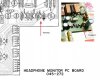
There is one other thing that I have found. On two boards there are differences in polarity on two capacitors. I have put red arrows and little comment on pictures.

Here is difference on headphones board. Polarity in mount view in service manual is different than polarity in schematic and board itself, and correct is like in schematic and board itself:

error_ph.jpg

On expander board correct is on schematic and on mounting view, and incorrect on board itself. Which means that capacitor was reversed mounted at factory:

error_exp.jpg

However both capacitors are in signal path, so reversing them will do no big harm.
 
A few McIntosh pieces of the same vintage as your C32 with cold solder Molex pin joints have haunted me in the past. To not reflow these solder joints while doing a recap would be restoration maleficence.

I currently have a friend's Arcam AVR300 Diva on the bench which has been haunting us for months with bad caps and cold solder joints by the dozens. I have hope that I found the last one just yesterday so the reflow issue is at the top of my list so to speak. Of coarse the vintage Mac solder issue's cause is different than the EU imposed solder issues of the last decade.
 
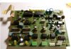
Today I am posting pictures of two small boards. The only change was new flat cable as old one was in very bas shape:

pair.jpg

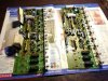
I must admit that I was a bit affraid of cables and their condition, but Gods of flat cables was very generous to my C32 and I all of them are in good condition. They all have a mask tape arround them to prevent splitting. One cable is missing at this picture, from LED board to switch board. I have not disconnected it from LED board.

flat1.jpg

Here are cables that I had to replace. They are all splitted and with oxidation at the ends. They were used on power supply board, switch board to expander board and small output boards:

flat2.jpg

Comming next:

next.jpg
 
Back
Top Bottom