

You are using an out of date browser. It may not display this or other websites correctly.
You should upgrade or use an alternative browser.
You should upgrade or use an alternative browser.
CA-1000 Rebuild Issues
- Thread starter jandajr
- Start date
Good question. I'm away from home so can't check my CA-1000, maybe someone can chime in, measuring resistance between the "C" wire and the -50 wire on each power amp board.What should be the "norm" reading for C to -50?
Probably path from C to R615, R614, R613, R605, R603, R604, R606, approx 20Kohms +/-10%.
Paths through TR605 should give OL
Yes, you can unsolder leads and remove board from chassis for resistance measurements.Can I do the same (ohms) testing, if I pull all the leads from the main board and remove the board from the chassis?
Trying to do the test is killing the ABCS leads. They keep breaking from turning and twisting the board. This would allow me to also double check all the components and PCB.
Would be nice if someone else chimed in with a resistance measurement from wire C to wire -50 on the power amp boards.

jandajr
Active Member
Lastest
C and -50V = 21.0 K
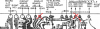
RED LINE: B(21K) thru VR603(21.0K) which is set at 00.0, thru R617(21.0K), thru R620(20.6K), thru TR605(00.1) at E, thru R619(0.0) to -50
Your path for C (mentioned above) is very different from the path illustrated on the image you posted from Friday Feb 11?
C and -50V = 21.0 K
RED LINE: B(21K) thru VR603(21.0K) which is set at 00.0, thru R617(21.0K), thru R620(20.6K), thru TR605(00.1) at E, thru R619(0.0) to -50
Your path for C (mentioned above) is very different from the path illustrated on the image you posted from Friday Feb 11?
Your path for C (mentioned above) is very different from the path illustrated on the image you posted from Friday Feb 11?
Response to question what should be normal C to -50Probably path from C to R615, R614, R613, R605, R603, R604, R606, approx 20Kohms +/-10%.
Paths through TR605 should give OL
This path was dismissed as a candidate when you measured 1.8k. The red line was the most likely candidate for 1.8k with faulty TR605.
Looks a bit strange, depending on meter probe orientation there is a path from TR605c to TR605b then R608/wire C. I don't see a 20.6k resistance. Following from markthefixer may be helpful with transistor testing.Lastest
C and -50V = 21.0 K
RED LINE: B(21K) thru VR603(21.0K) which is set at 00.0, thru R617(21.0K), thru R620(20.6K), thru TR605(00.1) at E, thru R619(0.0) to -50
jandajr
Active Member
OK, I'll admit that this amp
issue may be over my head, but I ran into this today and it doesn't make sense to me.
When checking the resistants on a circuit you stated "With one probe fixed on the -50 wire can you test/measure resistance at various points along this path"
I didn't think that it would make a difference if you put the Red+ lead or the black- lead on the -50 wire.
It apparently does, but I don't know why.
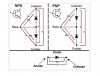
If I place the black- lead on the -50 wire and put the red+ on the TR605 collector pad I get 47.6K. TR605 was removed from PCB.
If I reverse the leads I get OL on the TR605 collector pad.
I'm hoping that I'm closing in on the problem, but now, who knows!
issue may be over my head, but I ran into this today and it doesn't make sense to me.
When checking the resistants on a circuit you stated "With one probe fixed on the -50 wire can you test/measure resistance at various points along this path"
I didn't think that it would make a difference if you put the Red+ lead or the black- lead on the -50 wire.
It apparently does, but I don't know why.
If I place the black- lead on the -50 wire and put the red+ on the TR605 collector pad I get 47.6K. TR605 was removed from PCB.
If I reverse the leads I get OL on the TR605 collector pad.
I'm hoping that I'm closing in on the problem, but now, who knows!
Think you should keep in mind the original problem (bias adj) caused by faulty voltages such as -50V(approx) at wire C. Early measurements showed 1.8k between wires C and -50, so a low(ish) resistance may have pointed to a shorted part, ie TR605c-e short.
47k is not of interest (to me at least), with TR605 removed is the MM current flowing through R615,613,610, TR601s-d,VR602,TR602b-e, R607, R603,4,6.
What happened to the 1.8K? Boards has been removed and wires unsoldered, check resistance between Wire C(brown) and the -50 wire(Violet) maybe problem is in the operations switch?
Whenever you reconnect everything back together can you unplug the right channel operations connector, careful not to short pins on AC wires then check for -50V at wire C.
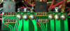
Then reconnect operations connector and remove both fuses from right channel power amp, again check for -50V at C.
47k is not of interest (to me at least), with TR605 removed is the MM current flowing through R615,613,610, TR601s-d,VR602,TR602b-e, R607, R603,4,6.
What happened to the 1.8K? Boards has been removed and wires unsoldered, check resistance between Wire C(brown) and the -50 wire(Violet) maybe problem is in the operations switch?
Whenever you reconnect everything back together can you unplug the right channel operations connector, careful not to short pins on AC wires then check for -50V at wire C.
Then reconnect operations connector and remove both fuses from right channel power amp, again check for -50V at C.
pure BS, well kinda...47k is not of interest (to me at least), with TR605 removed is the MM current flowing through R615,613,610, TR601s-d,VR602,TR602b-e, R607, R603,4,6.
you should not be reading 47k, the preferred path should be R615, R613, R605, 3,4,6=14.46k, MM current will be divided down other (eg red) paths so the 20.4k reading is not accurate (ie, in circuit measurements may be wrong).
You've done this same measurement a few times and got results 1.8k, 20.4k and 47k, suggests a bad solder connection causing intermittent contact. Maybe spend some time reflowing solder joints on right power amp, start with R605,6,4,3
Keep in mind VR603 is not zero on left ch. Don't see a connection to -50V at CRed or Black on -50 to C =20.4K
FYI
LEFT CHANNEL: Black on -50 to Red to TR605 "collector" pad 18.5K
Red on -50 to Black to TR605 "collector" pad 16.9K
jandajr
Active Member
Did you compile a parts list at the completion of your project?
I became a bit discouraged not being able to find the source of my problem, which was TR605 (collector) voltage at -50+ instead of -1.25. this voltage flows thru the leads S,C.B and A on the main amp board.
I'm an untrained "retired" hobbyist, who is flying by the seat of his pants.
Thanks for looking at my thread.
jandajr
Active Member
mbz / page 2 of this tread makes the suggestion to be able to test the board without TR609 & TR610.
Sorry, As far as the theory, you might want to reach out to "mbz".
As I stated earlier on this tread, I'm an untrained "retired" hobbyist, who is flying by the seat of his pants.
Sorry, As far as the theory, you might want to reach out to "mbz".
As I stated earlier on this tread, I'm an untrained "retired" hobbyist, who is flying by the seat of his pants.

Yamaha5000
Never settle for 2nd best
SD46 Diode, needing a replacement part #

Germanium diodeSD46 Diode, needing a replacement part #
https://www.tubesandmore.com/products/diode-1n34a-germanium-low-leakage
Last edited:
Yamaha5000
Never settle for 2nd best
Very interesting parts house
Yamaha5000
Never settle for 2nd best
I just noticed the NA numbers are not the same, what gives with that?


Last edited: