• The move to the new server is done. There are some software and database maintenance updates in process. This has us passing the hat around to help out. We appreciate any donations. Seriously, even a dollar helps. The payment page may be found here - https://www.audiokarma.org/support.html

Calbest 8211 stereo twin amplifier

teddyfreddy

New Member
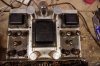
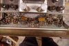
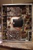
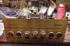
Hi all, I recently acquired a Calbest 8211, I brought it up on a variac and the left channel works, the right has a little hum and hiss and that's about it. First of all, would anybody know where I can find a schematic for this amp? It doesn't seem to be listed in the Sams photofact index. Also what are those two things that are cracked that are connected to the tone controls called? They're some type of capacitor combo pack right? Bare with me, I'm a bit of a newbie. I've always tinkered but never got in depth with electronics.
 

Attachments
  • IMGP3757.JPG
    IMGP3757.JPG
    89.8 KB · Views: 113
  • IMGP3758.JPG
    IMGP3758.JPG
    124.2 KB · Views: 113
  • IMGP3759.JPG
    IMGP3759.JPG
    115.6 KB · Views: 109
  • IMGP3755.JPG
    IMGP3755.JPG
    128.6 KB · Views: 103
  • IMGP3760.JPG
    IMGP3760.JPG
    41.8 KB · Views: 98
  • IMGP3761.JPG
    IMGP3761.JPG
    44.7 KB · Views: 98
Last edited:
Register to hide this ad
If you look at the tube location tag, someone scratched out what looks like QZ34/5AR4 and hand wrote 4U5 GB. The tube in the amp is a 5U4 GB.
 
yes and if you can find out the value of the components inside you can reproduce the circuit using regular caps and resistors.
The part number on them is pc-190. From my research so far it sounds like sometimes the schematics will list the individual component values that are contained in the p.e.c. If I can somehow find a schematic for this amp or a schematic from something else that contains the same p.e.cs it would be a big help.
 
yes and if you can find out the value of the components inside you can reproduce the circuit using regular caps and resistors.
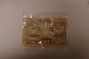
Well, I just purchased a Centralab PEC guide on Ebay. I attached an image from the ebay listing that has what I need! I figured I might as well buy the book in case I come across more of these bastards in the future.
 

Attachments

  • centralab pec pc190.jpg
    centralab pec pc190.jpg
    96.6 KB · Views: 39
The part number on them is pc-190. From my research so far it sounds like sometimes the schematics will list the individual component values that are contained in the p.e.c. If I can somehow find a schematic for this amp or a schematic from something else that contains the same p.e.cs it would be a big help.
Your best bet for now is finding 2 of the p.e.c components .Schematic wise for your amplifier is going to be a long shot to find since theres no sams photofact for it as you already know.im sure you checked ebay so i wont recommend that.
I dont know how how far you want to go with the restoration or your budget but it looks to be in good shape and should clean up nice .Forget the power rating it says it has on the label as its only good for about 15w per channel.as far as the rectifier tube is concerned itll work but i would put back in a gz34/ 5ar4a.Filter faps sound like they will need to be replaced as well if your getting hum.
 
Your best bet for now is finding 2 of the p.e.c components .Schematic wise for your amplifier is going to be a long shot to find since theres no sams photofact for it as you already know.im sure you checked ebay so i wont recommend that.
I dont know how how far you want to go with the restoration or your budget but it looks to be in good shape and should clean up nice .Forget the power rating it says it has on the label as its only good for about 15w per channel.as far as the rectifier tube is concerned itll work but i would put back in a gz34/ 5ar4a.Filter faps sound like they will need to be replaced as well if your getting hum.

It looks like nothing has really been tampered with in it either, everything looks original inside. The only things that i can tell have been replaced are some of the tubes. The wires that go to the controls all look melted at the ends where they connect. I wonder if they're actually melted due to heat or if it's age related degradation of the rubber insulation?
 
It looks like nothing has really been tampered with in it either, everything looks original inside. The only things that i can tell have been replaced are some of the tubes. The wires that go to the controls all look melted at the ends where they connect. I wonder if they're actually melted due to heat or if it's age related degradation of the rubber insulation?
Someoneone has done work to it.the rubber insulation your talking about is shrink tubing that you heat up with a lighter or other means to make sure the connection doesnt come into contact with other components but not nessceray needed.
 
Someoneone has done work to it.the rubber insulation your talking about is shrink tubing that you heat up with a lighter or other means to make sure the connection doesnt come into contact with other components but not nessceray needed.
I have used shring tubing before, this looks different. More like melted goop.
 
Yeah, looks like someone's been in there with a 100W iron. And, be sure to get that 5U4 out and replace it with the proper rectifier.
 
EL84 push-pull with reasonable size output transformers you can expect 15 watts or so, maybe a smidge more depending on the voltages. This thing looks reasonably built. Shame about the circuit boards, the old ones are a PITA but hopefully they aren't so bad that it can't be re-worked.
 
Back
Top Bottom