• The move to the new server is done. There are some software and database maintenance updates in process. This has us passing the hat around to help out. We appreciate any donations. Seriously, even a dollar helps. The payment page may be found here - https://www.audiokarma.org/support.html

Can I use a Russian 6P15P-EV in place of a 6BQ5/EL84/6P14P-EV in my PP amp?

spantou01

AK Subscriber
Subscriber
Many of us have come to depend on Russian 6P14P-EV tubes for our Dynaco SCA35, Fisher SA-100 and other 6BQ5 based amplifiers, where the output tubes are running close to the voltage and dissipation limits. With the scarcity of 6P14P and its variants at the moment one wonders to what degree and under what operating conditions 6P15P-EV would work satisfactorily in an amp designed for 6BQ5 type tubes. I have a box of them and they seem to be considerably less expensive to buy, even now, than “real” 6P14P-EVs.

If you search the internet for an answer to the question in the thread heading you will find many warnings that 6P15P-EV is a fragile tube, but no direct answers. I have been trying to get at the bottom of the anecdotal: “they are more fragile than …”. I know what the spec sheet says, but the Russian specs are notoriously conservative.

Has anyone reading this actually tried 6P15P-EV in place of 6P14P-EV and experienced failures? Presumably screen failures. If so, was it in UL mode, pentode and at what screen voltage? I have scoured the internet and found many “they are more fragile” references, but have not found any evidence of someone who actually tried it and experienced failure in this swap. If you have experience with this we would love to hear about it. I do know of someone that used 6P15P-EV successfully in his Baby Huey build, but he had variable screen voltage and monitored screen current.

I wanted to determine this for myself, so I’m currently building a Tubelabs SPP (Simple Push-Pull) amp (http://tubelab.com/designs/tubelab-spp/) and adding fixed bias based on Dave Gillespies’ EFB design and variable screen voltage (in pentode mode). I plan to run the 6BQ5 power tubes at 320V (plate to cathode) and screen supply voltage variable between 200V and ~300V, and compare performance under these conditions with 6P15P-EV. I also will connect UL output transformers if the first experiments work well. I will report what I found. Unfortunately I do not have the capability to measure distortion.
 
Last edited:
Register to hide this ad
If you search the internet for an answer to the question in the thread heading you will find many warnings that 6P15P-EV is a fragile tube, but no direct answers. I have been trying to get at the bottom of the anecdotal: “they are more fragile than …”.
As with any tube, just don't exceed the data sheet specs.

https://tubedata.edebris.com/sheets/113/6/6P15P.pdf

The values listed under "Electrical Characteristics" are the recommended operating points. For G2 they suggest a voltage of 150v and current of 4.5mA with maximum of 6.5mA.

Here's a thread from AA that should answer your question:

https://www.audioasylum.com/cgi/t.mpl?f=tubes&m=196511
 
Re: Eli's comment . . . "Another problem is the pin out. G3 is not connected to the cathode internally. The good news is that sockets wired for the 6p15p accept EL84s without incident."

The 6P15P is not a drop in replacement for sockets that are wired for 6BQ5 / EL84. You must connect G3 (pin 6) of the 6P15P to the cathode (pin 3) at the socket because it's not connected internally. On the 6BQ5 this connection is made internally.
 
As with any tube, just don't exceed the data sheet specs.

https://tubedata.edebris.com/sheets/113/6/6P15P.pdf

The values listed under "Electrical Characteristics" are the recommended operating points. For G2 they suggest a voltage of 150v and current of 4.5mA with maximum of 6.5mA.

Thanks for your speedy reply. You are quoting the specs that I had previously looked at, and that is sound advice. (So does Tom Bavis in his reply on diyAudio as well as Eli Duttman). But it is more complicated that this. As stated, I believe the Russian specs are conservative and I would like to know what is possible (and advisable) under real world conditions. Hence my request for comments from people who actually tried these tubes.

You are right, of course, under "Electrical Characteristics" (for 6P15P) they list a screen (Ug2) voltage of 150v and current (Ig2) of 4.5mA with maximum of 6.5mA. However, as Nerdorama mentioned above, the both maximum Ug2 and Ua (plate voltage) are given as 330V, and max Pg2=1.5 W as you mentioned. Pa=12 watts, same as 6BQ5. For 6P14P the same source lists “Electrical Characteristics” as Ua and Ug2 both 250V and Ig2=5 ma and max 7 ma. But we know that 6P14Ps are frequently used and deliver good service at much higher voltages. The maximum listed for 6P14P on the datasheet is Ua=300, Ug2=300V, compared to 330 V for the 6P15P. Pa=14 W max (exceeds 6BQ5 spec), and Pg2=2.2 max.

The question is if the 6P15P-EV can function successfully in an amplifier designed for 6BQ5, and even ones that run the 6BQ5s hard. Perhaps. That is what I’m trying to determine and under what operation conditions could they substitute. For example, in Dave Gillespie’s Fisher SA-100 clone, he has approximately 410V from plate to cathode of
Genalex Gold Lion EL84/N709, which after 2000 hours showed little wear. Note that these tubes have standard EL 84 specs with Ua maximum=300V (https://www.tubesandmore.com/sites/default/files/associated_files/t-el84-gen_specification_sheet.pdf) I asked Dave about that and he explained in post #112 here: https://audiokarma.org/forums/index...fisher-sa-100-clone-in-progress.466229/page-6

Klausmobile has a website with some interesting information on Russian tubes. http://www.klausmobile.narod.ru/testerfiles/6p15p.htm
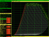
Below is a triode trace that he performed (with 6P14P and 6P15P-EV) and superimposed. He concluded:” Here an EL84 (Saratov 2000) curve set is superimposed on 6P15P curves... or the other way around ... who cares - they are identical.”

upload_2022-6-25_16-46-55.gifBelow
 
Last edited:
I have run 6P15P tubes in amps that run under 300 volts on the plate, and they work very well. I've never truly stress-tested one to see at what point it blows up though. Without measuring it, offhand I want to say both plate and screen are really close to 285v to ground. It runs EFB, so the cathode is probably roughly 15v to ground so effectively 260-ish across the tube.

I have run 6P14P-EV, EL84M, 6BQ5, and Euro EL84 in that amp, and according to the test gear they all perform within spitting distance of one another.
 
I believe the Russian specs are conservative and I would like to know what is possible (and advisable) under real world conditions.
Both Eli (who doesn't post here) and @Tom Bavis are pretty sharp guys so I'd consider their comments be fall under "what's advisable". As for "what's possible", you may have to be the one who torture tests them to find their true limits.
The question is if the 6P15P-EV can function successfully in an amplifier designed for 6BQ5, and even ones that run the 6BQ5s hard. . . . . For example, in Dave Gillespie’s Fisher SA-100 clone, he has approximately 410V from plate to cathode of
Genalex Gold Lion EL84/N709, which after 2000 hours showed little wear.
Of course, all tubes have their maximum ratings in addition to the operating points that are listed under "typical operation" and people often push things a bit.

I haven't read Dave's Fisher SA-100 thread but despite the high plate voltage I'd be surprised if he's running the tubes beyond their dissipation limit. It's the dissipation limit that's most important, as I mentioned in that other thread:

https://www.audiokarma.org/forums/i...ith-heathkit-iron.978436/page-2#post-15712037

I just don't see the point, unless it's for bragging rights. As I posted on that other thread earlier:

Squeezing as much power as you can out of the tube won't produce enough of an increase in sound level to be noticeable, even if you run the amp at full volume. It will, however, reduce the life of the tubes and increase the chance of failure. So what's the point?

It takes 2x the power to produce a 3db increase from the speaker. If you leave the volume alone and stand ~39 inches closer to the speaker, that's a 3db increase. So suppose you push the tubes and get 10% more power at maximum output. That's 0.3 db which is the equivalent of standing a few inches closer to the speaker. But again, that's if you run the amp wide open. At normal listening volumes it would be the equivalent of tilting your head forward.
 
FlaCharlie, I agree with what you said, and I have nothing but respect and appreciation for Tom Bavis and Eli. Dave Gillespie’s Fisher SA-100 clone carefully complies with 6BQ5 dissipation specs, by using a relatively low quiescent current, 23 ma per tube IIRC. The point is, as Dave explained, voltage specs could be exceeded, if one knows what you are doing. I hope to learn that part about the 6P15P-EV from folks with experience and my upcoming experimentation.

So, the quest is not to maximize power output of a newly designed amp built to use 6P15P-EV tubes. In stead it is to find a less expensive alternative to 6P14P tubes, especially the military EV versions, that became quite expensive in recent months, and define the conditions under which the substitution would safely work. 6P15P-EV are still relatively inexpensive and available. I think it would be helpful to many to know how and when to use them, especially in existing 6BQ5 amplifiers.
 
Last edited:
the cheapness (and a mistake) is why I bought mine. Years ago they were something like 1/3 the cost of the 6P14P-EV back when that was considered the good, cheap tube.
 
I have run 6P15P tubes in amps that run under 300 volts on the plate, and they work very well. I've never truly stress-tested one to see at what point it blows up though. Without measuring it, offhand I want to say both plate and screen are really close to 285v to ground. It runs EFB, so the cathode is probably roughly 15v to ground so effectively 260-ish across the tube.

Good! We have a data point that 6P15P works well at about 260 Vdc across the tube for both screen and plate. What amps did you use them in?

I checked and 6P15P-EV is still available for 1/2 the price of 6P14P-EV, from sellers in Romania, and less from sellers in Ukraine. I have received tubes from Ukraine recently, so some sellers are able to ship (presumably from the western side).
 
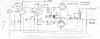
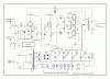
I actually dug that schematic up last night, based on what I noted on it, its actually closer to 295 volts across the tube.

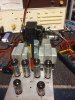
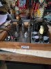
It started life as a Madison-Fielding console amp but it has transformers from a Hammond tone cabinet. The originals were 2.5 ohm output, which isn't real useful. The Hammonds were cheap, fit, and run at 8 ohms.

I noticed I forgot to fix something on that schematic. The front end is a 12ax7. That was modified from the original schematic I drew. When the amp showed up it had 12AU7 tubes, so thats what I wrote on it. Further investigation showed the values used on the socket made no sense for a 12au7 but did make sense for a 12ax7. Circuit remains stock, just with some tweaks for different output transformers, plus I installed an EFB regulator in place of the cathode resistors.

1109171912a.jpg 20171101 schematic.jpg 20171028 MF top resized.jpg
 
The point is, as Dave explained, voltage specs could be exceeded, if one knows what you are doing.
There's nothing mysterious about it. All that's necessary is to calculate the dissipation based on the data sheet. If you want to run higher voltage you just lower the current to compensate. It's just basic Ohm's Law: V (voltage) x I (current) = W (watts of dissipation). Various combinations of voltage and current can be used but it's best to stay within the "Typical Operation" dissipation limits in the data sheet.

So, the quest is not to maximize power output of a newly designed amp built to use 6P15P-EV tubes. In stead it is to find a less expensive alternative to 6P14P tubes, especially the military EV versions, that became quite expensive in recent months, and define the conditions under which the substitution would safely work. 6P15P-EV are still relatively inexpensive and available. I think it would be helpful to many to know how and when to use them, especially in existing 6BQ5 amplifiers.
If maximum power is not the main goal then running somewhere between 75% and 90% of those limits should ensure reliability which is always a good thing, even if the tubes are available and cheap. And, as I pointed out, running them hard offers no advantage in terms of increased volume under normal conditions.

I'm certainly all for using less expensive and alternative tube types. I've modded a SE 8300 Magnavox amp to use 12BH7s in place of 6BQ5s, a PP Maggie 8800 6V6 to use directly heated Russian 4P1L outputs and a Maggie 175/185 6V6 to use 6N6G outputs. See my comment about "interesting tubes" in my signature. :thumbsup:

If you're actually building something from scratch based on the Tubelab board and you're designing around these tubes, you have more options than you would if you were retrofitting an existing 6BQ5 amp and were stuck with using its existing power supply. That's because you can choose a power transformer.

"How to use them" in an existing 6BQ5 amp is pretty basic. As pointed out earlier, you need to make a connection between Pin 6 (G3) and Pin 3 (K) at the socket since they are not connected internally like they are with a 6BQ5. Then just stay within the dissipation limits that are in the data sheet.

When modding an existing amp the PS voltages can be adjusted a bit but mostly you just make sure the current flow through the tube doesn't result in too much dissipation. Specifics would depend on the specs of the existing PS.

In either case, the free PSUD2 program can be used to dial it in.

The plate voltage / dissipation of these tubes has never been an issue, it's only the screen dissipation that you need to watch out for. I'd start by following Tom's advice in that AA thread and put a 10k resistor on the screen pin. Then just use Ohm's Law to calculate the screen current and dissipation and make adjustments as necessary.
 
oh, yea I did forget about the G3 thing. I actually forgot that when I put that Madison-Fielding amp together. It actually works with that not connected but it has a slight bit of fuzz to the sound that you notice after a while. Handily, having the jumper in there doesn't affect use with a 6bq5 so I can run either tube in that amplifier. I just leave the 6P15P because I have nothing else I'm confident they will run in.
 
I do know of someone that used 6P15P-EV successfully in his Baby Huey build, but he had variable screen voltage and monitored screen current.

I have now confirmed this “data point” He wrote: “I am using the 6P15P-EV in an el84 baby Huey. I reduce the plate current to keep the screen dissipation below 1.5w. I think I am running 300v and 30ma on the plate if memory serves. The power out is slightly less than EL84 at 10 or 11 watts”.

Note that this build is using fixed bias and Toroidy EL84, 8k output transformers in UL connection, with regulated plate supply. If remembered correctly he found that 300V plate to cathode does keep the screen dissipation under 1.5 watts. This setup has been performing well for over two years now, at “datasheet max”screen dissipation rate.
 
Last edited:
Reviving this old thread , confirming the last data. Because I could get an octet new 6p15p-ev for the price of one new 6p14p-ev , I adapted an audionote el84 pp board to fit the 6p15p-ev. Modifications included adding UL connections for G2 with 240Ohm screen resistor, 180 Ohm per individual tube cathode resistor and connect pin3 and 6. HT was 280Vdc (218Vac) which resulted in a quiescent current of 36 mA per tube and ca. 6.7V over the cathode resistor. With the used OPT, 7.6K with UL taps at 43%, this gave 274V on the plate and g2. The measured g2 current was 5mA, which is 1.33 watt , and combined plate+g2 power is 9.6 watts. Ouput power was 9.2V over 8.2 resistor which is ca. 10Watt. Power output was the same 9.2V when connected as pentode and a shared g2 resistor of 430 Ohm, so I run it UL connected, which is allso better with regards to g2 power , as when g2 current increases the voltage on g2 allso considerably lowers because of the UL connection. Measured 277Vac over plate to plate and 125Vac g2 to g2 at full 10 Watts out. This is the original board not showing my mods for the 6p15p-ev. Next mod will be changing to controlled fixed bias per tube.
ANK_EL84_REV_E_add_LED_(2).gif
 
Last edited:
I just installed 6P14P-K's in a moddified Magnavox 9303 console amplifier.
So far Nice sounding tubes. They're only rated for 3000 hours though, but for the price I can't complain.
 

Attachments

  • 20221221_110514.jpg
    20221221_110514.jpg
    139 KB · Views: 27
Reviving this old thread , confirming the last data. …..Power output was the same 9.2V when connected as pentode and a shared g2 resistor of 430 Ohm, so I run it UL connected, which is allso better with regards to g2 power , as when g2 current increases the voltage on g2 allso considerably lowers because of the UL ….. This is the original board not showing my mods for the 6p15p-ev. Next mod will be changing to controlled fixed bias per tube.

Thanks for this post. I am still building my test mule using the Tubelab SPP boards as described earlier, to be able to try various operating conditions for PP 6P16P-ev. But alas, it is going slower than hoped for. Your “reviving” of the thread is welcome.

So, when you ran the 6P15P-EV in pentode mode what was the g2 voltage? Could you explain the following please: “which is allso better with regards to g2 power , as when g2 current increases the voltage on g2 allso considerably lowers because of the UL”
 
Pentode mode is hardest on the screen - as plate voltage goes down, screen current goes up. Triode mode is easy on the screen, since screen voltage is no higher than plate. UL is in between, screen voltage goes down as plate goes down, but not as much.
 
Well stated. For my 6P15P pentode experiments I will use Dave Gillespie’s EFB II scheme to modulate the final tube’s screen voltage in fixed relation to the plate voltage. My working hypothesis is that the 6P15P will perform as well as 6P14P/El84 under these operating conditions where the screen dissipation can be appropriately controlled.

Hence my question to @systux’s about what q2 voltage was in his case. From his data points above (and others I have heard of) it seems that power output is lower for 6P15P than EL84. I hypothesize that when the screen voltage is set properly for the 6P15P it will behave and perform like an EL 84, including power output. It would be great if someone with a tube tracer could run some curves like that, but I don’t have access to such tracing.
 
These old stock tubes are surplus from the soviet era being sold by people in the now free eastern European countries. So, buy Ukrainian and stick a finger in Putin's eye. :D I haven't bought any new manufacture Russian tubes since all this started. I tend to buy JJ signal tubes anyway when buying new manufacture.
 
Back
Top Bottom