• The move to the new server is done. There are some software and database maintenance updates in process. This has us passing the hat around to help out. We appreciate any donations. Seriously, even a dollar helps. The payment page may be found here - https://www.audiokarma.org/support.html

Cant Set Bias On Concept 11.0

Do you have a laser thermo sensor? The temp of each output may yield a clue. Also might be good to scan temps of the components in front of outputs.
 
Bias seems OK but temps should be slightly above room temp on idle

Please check the following:
1. Base resistors for all 8 outputs - should be 4.7R
2. Output sockets - the transistor have a snug fit without loose connections (B,E pins)
3. Bias transistor replaced with KSC2690 (or KSC2383)
4. Check for any high frequency oscillations during idle or load
5. Turn bias pots down (may be below 2mV) and check temps.

1. they all measure 4.7 ohms.

2.I tested and cleaned the sockets for the outputs, the measure well

3. TR506 is KSC2383OTA, I do have a some 2690's which I could try.

4. I haven't noticed any oscillation with the Toshiba drivers, I drove the amp pretty hard from 20hz-20khz using a restored Heathkit 5218 as a source and the sine waves look extremely clean, even the square waves look good.

5.I lowered the bias to 2mv and the amp still gets hot. The components that get hot are R510 (connected to the zener, its kind of hard to spot on the schematic), TR505 (TTA004B), TR503, and TR504 (KSC3503DS, I tried KSC2690 but the distortion pictured in my first post came back, this was after I put the Toshiba drivers in).


Do you have a service manual for the 11.0, I could only find the schematic for it online

Edit: I am starting to get pretty suspect of the output transistors will put in the originals tomorrow to see if anything changes.

 
Last edited:
Unfortunately I don't. I have a 11.0 waiting to be restored. I have been following the schematic trying to help you. Good to know what you found on TR503 and TR504. Good to know. I like the idea of putting the originals back. I am assuming you sourced the current outputs from Digikey/Mouser.

TR506 - KSC2690 is more beefier. I would try this.
 
Unfortunately I don't. I have a 11.0 waiting to be restored. I have been following the schematic trying to help you. Good to know what you found on TR503 and TR504. Good to know. I like the idea of putting the originals back. I am assuming you sourced the current outputs from Digikey/Mouser.

TR506 - KSC2690 is more beefier. I would try this.

Okay, thanks ill try the 2690's for bias if that does nothing ill start to undo what I've done to the unit so far.

The big reason I haven't put the original driver back in is because i use mica instead of sil-pads and really don't enjoy the mess grease makes.

Its super annoying when everything in and amp works well but there is still a major issue, the receiver itself sounds fantastic but I doubt it would last long with the amount of heat it puts out.

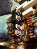
Also since photos are cool here's what the blown channel looked like, definitely the worst if seen so far. The heat turned the board to charcoal and de-anodized the heatsink.
IMG_20230416_181054570.jpg IMG_20230416_013808125.jpg
 
WOW - that looks bad. even the ceramic cap looks roasted. Can you post a pic of the restored board as well?
 
Sorry for the delay on the update, I honestly got tired of working on the concept and finished a few other projects that were more straightforward.

I ended up putting in each original transistor one by one and testing but the heat problem still remained, I'm still really confused because like I said, other than the heat the unit functions very well, I can add heatsinks to 504 and 505 but the big issue is the temp of the outputs, they don't idle hot but when driven hard they can really heat up the heatsink.

I did find a video on the 16.5 form a really good tech and he stated that 504 and 505 in the 16.5 idled at around 160 degrees so maybe the receivers ran hot out of the box.:dunno:

I'm thinking of adding some good sized heatsinks to the unit and running it for a week or two before deciding what to do with it.

Also ill post some photos of the board, I ended up filling the hole with some epoxy and drilling holes for the transistor pins, its not the best looking job but it works and can be reversed

11:08 in the video
 
Back
Top Bottom