• The move to the new server is done. There are some software and database maintenance updates in process. This has us passing the hat around to help out. We appreciate any donations. Seriously, even a dollar helps. The payment page may be found here - https://www.audiokarma.org/support.html

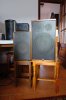
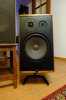
Canton Quinto 540

Sweet! You did really really nice work and made some good choices. ;) And of course you are very welcome for any help that I was able to give. As far as I'm concerned one of the major reasons to build experience is to share it.

Enjoy the fruits of your work!
James
 
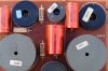
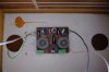
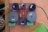
Maybe there are two versions of the filter? In my quintos 540 they look more like this.
(I'll upload the original photos tomorrow).
Thanks.

18518038_1921078001471850_1974110633969564322_o.jpg
 
Last edited:

Hi James,

I found a post about the caps used in Quinto 540:

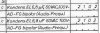
1182: Wego Elko glatt 35 VAC 4N ALR/U bipolar GPF (4 cm × 2,5 cm) 56 ųF.
1183: Wego Elko glatt 35 VAC 7N ALR/U bipolar GPF (3,5 cm × 1,6 cm) 15 ųF
3098: Wego Elko glatt 25 VAC 9N ALR/UTFZ/TM (3,5 cm × 1,4 cm) 18 ųF

ref: http://www.hifi-forum.de/viewthread-225-4457.html

So I am going to recap my Quinto 540. Where would you recommend to purchase the caps? I know only Conrad.

Regards,
Tony

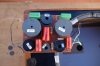
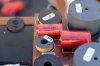
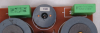
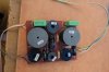
I was referring to this, my crossover has a different appearance, and one of the caps seem to be different as well, there is not the 3098, but i have a 1102.....

"1102 = 22µF/23vac", thanks to Bratwurst7s, this is correct?
 

Attachments

  • DSCF1141.JPG
    DSCF1141.JPG
    83.3 KB · Views: 55
  • DSCF1140.JPG
    DSCF1140.JPG
    84 KB · Views: 50
  • DSCF1145.JPG
    DSCF1145.JPG
    81.9 KB · Views: 51
Last edited:
reading in German forums I learned that the number printed inside referred to the number of week and year, then my fifths would be of week 21 of the year 1981...
and those of the companion would be 1983
 

Attachments

  • DSCF1144.JPG
    DSCF1144.JPG
    81 KB · Views: 21
The Canton Quinto 540 looks a lot like my Karat 300's. Luckily they had been recapped by the previous owner. Besides the tweeter placement they look like twins. Mine are the 4ohm version. I was powering them with an Outlaw RR2160 receiver and it did a good job. Got to thinking something with more power would help. They are now powered by a Parasound 2250 v.2 amp and Parasound 200 pre and it certainly opened them up. Headroom in an amp can make a big difference.
 
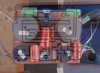
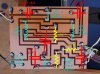
I made a photo montage to overlay both sides of the circuit, in case it's useful for someone who knows more electronically than me (anyone really...)
 

Attachments

  • crossover quinto 540.png
    crossover quinto 540.png
    925.2 KB · Views: 45
It's definitely different from Tony124's
Here a diagram of mine
View attachment 2857364
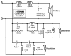
That was clever inverting the solder side image and overlaying the component side. Here's a schematic derived from your labeled diagram:

Quinto 540_pepoyaso.png

Besides parts value differences, yours also has 1 less resistor and 1 less capacitor compared to the OP's assembly. It would be interesting to see circuit details, but a schematic of the OP's version can't be traced with certainty without a solder-side image for reference.
 
Last edited:
Thank you very much Stuart, this is pure gold for me and I guess for many others,
I think this is the first time it has been posted on the internet
(believe me, I've given it two full laps looking for it).
Studying it I have noticed a couple of errata (I think),
referring to the film capacitors that are in front of the tweeter,
both are marked "MKT 1822" but show different values, 6,8 and 8,2μF respectively.
I think it's because "1822" is referred to the Vishay line and "M9" and "N2" to the model

Attached pdf with the series.
https://www.vishay.com/docs/26012/mkt1822.pdf

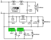
So the diagram would look like this?

Thank you again

MKT 540.png

mkt 540-2.png
 
Last edited:
Studying it I have noticed a couple of errata (I think),
referring to the film capacitors that are in front of the tweeter,
both are marked "MKT 1822" but show different values, 6,8 and 8,2μF respectively.
I think it's because "1822" is referred to the Vishay line and "M9" and "N2" to the model

So the diagram would look like this?
Never hurts to include component details into the schematic. I was just going with the minimum; Canton ID number and part value. Number for the 8.2µF cap is identified as 2525 on Tony124's board which has that exact part. His assembly is advantaged by small labels to the side of components as well as screen printed beneath them.
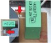
2525 cap.jpg

There are ample references to ID no. 1611 for 6.8µF, 100V caps in both foil and electrolytic. But this number "2" peeking out from under your cap gave me pause from labeling it on the schematic:
Cap-ID-Peek.jpg

Canton documents for CT 2000 (posted at opweb.de) list 6.8µF, 100V with ID no. 2102, for foil caps ...
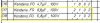
CT 2000 2102 caps.jpg
... as well as electrolytic

CT 2000 BP 2102 caps.jpg

Though I still hesitate from so labeling the schematic for two reasons:

1) Reluctance to assume without verification that the whole screen printed number reads "2102." Maybe there's yet a third ID assigned to some 6.8µF caps.(?)

2) There's an additional hole drilled that could accommodate a cap having longer lead spacing. Perhaps 2102 differs by having a longer footprint, but the PCB design allows substituting 1611 sized caps. In which case that Roederstein MKT1822 series capacitor might actually be catalogued by Canton as 1611.

It's a mystery I'm still researching, hoping to definitively update the schematic in post #49. Fill free to modify the schematic any way you feel is useful. You're obviously adept with digital graphics. And crossover assembly details are at your fingertips.:thumbsup:
 
Again, thank you for so much knowledge.
I was also struck by the pre-drilled holes, I assumed it was an improvement in the capacitor,
but it was not very safe.
I am about to open a specific thread of the restoration of my canton quinto 540,
internal and external, but as you are helping me so much here,
I would like to ask you if the capacitors that I have acquired (quickly, because of the closeness) seem valid to you,
I do not expect them to last another 40 years, I do not think that myself lasts so long....

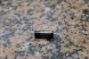
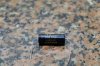
DSCF1184.JPG DSCF1184.JPG DSCF1183.JPG DSCF1182.JPG
 

Attachments

  • DSCF1181.JPG
    DSCF1181.JPG
    90.1 KB · Views: 5
... I would like to ask you if the capacitors that I have acquired (quickly, because of the closeness) seem valid to you,
I do not expect them to last another 40 years, I do not think that myself lasts so long....
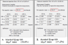
I personally have high regard for Mundorf ECaps as replacement for original electrolytic. With an exceptionally tight tolerance rating of ±5% they often measure even better than that, such as these I've recently measured using DATS 3:

Mundorf A-B.png
They're a fine improvement over the aged stock caps, without the fuss of adding series resistance to compensate for lower ESR if switching to film caps.
 
I am glad to know that, I distrusted a bit of performance for its low price (compared to other options)
in total the six capacitors cost me 14 €.
I get to the task of doing the recap.
Thanks again Stuart.
 
Someone has sent me a private message asking me if I noticed improvements after the change of capacitors, I make public the answer, in case there was anyone with doubts, beyond the improvement of the sound, which can be subjective..., now the three speakers are "joined," the ear must be close to almost glued to distinguish the sound emission between medium and tweeter, from more than 50 cm the complete sound comes out of the front, there are not three point sources, only one.
Amazing for such a big speaker
 
Back
Top Bottom