• The move to the new server is done. There are some software and database maintenance updates in process. This has us passing the hat around to help out. We appreciate any donations. Seriously, even a dollar helps. The payment page may be found here - https://www.audiokarma.org/support.html

Cap Coupled Receivers?

Idle current is set just like any other Marantz receiver. Just follow service manual for test points. You don't adjust DC Offset. There is no way to get the speaker terminals to zero VDC.

Thank you. So are you saying DC offset is not adjustable applies to ANY cap coupled receiver ?
 
Thank you. So are you saying DC offset is not adjustable applies to ANY cap coupled receiver ?
Well, I'm not educated enough to know the answer to that. But it would seem that since essentially rail voltage - with no offsetting opposite polarity voltage - is present at the speaker terminals, there would be no offset to adjust. Maybe someone can explain it for those of us with shallow knowledge of circuit design.
 
Well, I'm not educated enough to know the answer to that. But it would seem that since essentially rail voltage - with no offsetting opposite polarity voltage - is present at the speaker terminals, there would be no offset to adjust. Maybe someone can explain it for those of us with shallow knowledge of circuit design.

Hopefully there will be some more contributions. Thanks !
 
You don't adjust DC Offset. There is no way to get the speaker terminals to zero VDC.
There is an adjustment many cap coupled amps have that does essentially the same thing as the DC offset adjustment.

**First, remember a DC coupled amp has a positive and negative supply rails, and a cap coupled amp has a positive rail, and ground (0V).

What some service manuals will tell you to do is do a power output test with 8ohm dummy loads, signal generator, and scope. First, the amp is turned up to where clipping just starts. You then adjust a variable resistor so both the top and bottom of the sinewave clip at the same time. This is basically doing the same thing as a DC offset adjustment in a DC coupled receiver. You are balancing the amp so the output is right in between the two rails. The output DC voltage should be in the middle of the rail voltages. In a DC coupled amp, this point is 0V. In a cap coupled amp, it is between 0 and the positive rail voltage. If you take a DC coupled receiver with the offset way off and did a power test, you would also find one half of the wave clipped before the other half, because the signal was closer to one of the voltage rails than the other.
 
basically with cap coupled one output transistor runs about half voltage of the other . hence the need for the dc blocking cap .
not because its half the voltage ..its because the dc voltage is there .
 
Trivia- Back when the cap coupled receivers were made, caps were really inexpensive. My guess is because receiver manufacturers probably contracted with only one or two cap companies for most of their needs, they got 'em even cheaper. I'm not talking about higher quantities of a single part, but a deal for an entire group of parts. Going with cap coupling meant a slightly cheaper power supply and generally low complexity. It was done for economy and I'd be surprised if it was ever touted for sound quality, internally or in the marketplace. It's just a pleasant surprise that today we find the sound has its own qualities that many prefer.

I don't know if this is paranoia or has ever happened, but I can imagine a scenario where an output cap sits at half the supply voltage for decades. Over time, exceeding that voltage will cause increased leakage and failure if the cap doesn't reform. At a certain age reforming might be a long process. Now, let's say the high side output transistor in the old amp fails and shorts. The cap now sees the full supply voltage that it used to be rated for, but can no longer handle. Goodbye woofer perhaps? As I say, it might be paranoia, but if the caps can't be tested to full voltage, it makes a lot of sense to replace them. BTW, even though the signal might swing the full supply voltage, the cap never sees that- it passes the audio frequencies. Technically, you could use a 30 volt cap with a 60 volt supply, though no sane person would.

 
It's just a pleasant surprise that today we find the sound has its own qualities that many prefer.
It is technically a distorted and less true sound. But in a way some find pleasing.

There were a couple pages in a text book at the university library from which I got a lot of the information that went into my original post in this thread.
I should try to make it back there and scan them for you guys.

There were graphs that showed how the "distortion" decreased as you increased the quality or capacitance of the coupling cap.

And what I'm referring to as distortion might be better described as a skewing of the frequency response.
 
Last edited:
For starters, can I do a DC offset check on my cap coupled receiver as follows ? : 1.) Receiver on AUX., 2.) Volume @ 0., 3.) Balance centered & tone controls flat, correct ?
Then do I set my MM to mV or whole volts @ the lowest setting & check for existing DC voltage @ the L & R speaker terminals ?
Thanks for your help & patience guys !
 
you check voltages at the output transistors collectors . one should be about half the voltage of the other one .
 
I wouldnt know how to locate them. I'll post pics a little later. Btw, It's equipped with STKs on a heatsink if that changes anything.
Thanks !
 
In general, measure the power supply voltage with a DVM. Set the voltage on the not-speaker-side of the output cap to half that. The result will be slightly too high, but close enough.

The setting is always a compromise because the power supply voltage will sag under load. If you use a scope and set for symmetrical clipping with a sine wave, you'll get different results if one or both channels are driven, and different results with different (4 or 8 ohm) loads. Since music isn't a sine wave and will draw less current for the same peak amplitudes, you'll get different results for music. If you change the value of the power supply filter cap, you'll get yet more different results. In theory the circuit should proportion to the supply over some (low) bandwidth but IMO too many variables to get any precision in the matter. If I want to do better, I play my favorite song into my favorite load, both channels, and set for equal onset of clipping with a scope. That would probably be Deep Purple Perfect Stranger into 6 ohms but YMMV.
 
Last edited:
what receiver model is it ?

It's a GE RA200A Stereo Receiver, not much, powerwise either, but I luv the little _____ thing & it looks & sounds really nice & has the potential to sound better with a little work. I bought 1 brand new in '75 & returned it for something with a little
more power & have regretted doing it ever since. I found the 1 I have now on the web & it's in very good shape cosmetically & pretty good functionally. Awful glad to have another one. Perfect for a bedroom !

I'm new to this stuff & hopefully I'll be able to improve some of its performance myself with help from this site. Thanks !

PS: I tried to check DC offset a few times but my DMM is so sensitive I'm not sure of the results & if I did it right. L&R :+/- 6mV ?
Gut pics later today hopefully !
 
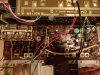
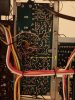
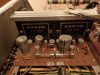
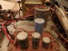
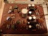
Ok, here's some pics of the GE receiver's guts. Some pots on the tuning PC board are in question,
with 1 on the bottom of the board. I'm not sure if this unit has any pots for DC offset or idle current.
Also wondering why the + wire on the large cap got a little warm ! It's been running luke warm
since I've had it, or so I thought. Any help would be greatly appreciated. Thanks guys !!


PB030241.JPG PB030246.JPG PB030242.JPG PB030243.JPG PB030244.JPG
 
pic 1 is the tuner do not touch that .
the driver board doesn't appear to have any adjustments .
all you can do is renew the capacitors and check resistors are still in tolerance .
 
pic 1 is the tuner do not touch that .
the driver board doesn't appear to have any adjustments .
all you can do is renew the capacitors and check resistors are still in tolerance .

Thanks ! Which 1 is the driver board ? Also, are there places I can @ least check the idle current ?
Cheers !!
 
driver board is one with stk packs attached .
nothing for idle current .its all done inside the packs

Thanks again. If I check the DC offset @ the speaker outs, does my DMM need to be set on mV, or can I use the lowest setting for whole volts ?
Now I'm gettin' somewhere !
 
if it's cap coupled and no speakers attached, you will probably be getting volts. On my 2230, it is something like 26V.
 
Back
Top Bottom