JamesWest...
New Member
Hello dwellers of the Marantz subforum.  I am seeking knowledge about a Marantz 1150 (not the D model). This amp is a friends, and they asked me to take a look at it. I have a rudimentary knowledge of electronics (mainly tinkering with them for fun) and can solder confidently.
A bit of Context:
Here's the story of what happened. I did some work on the amp for my friend because one channel was fuzzy and cut in and out. Cleaning the pots and switches with contact cleaner fixed it right up, but I also found the main power switch was toast (literally melted) so I swapped it and the snubber out for a new replacement kit I got off Ebay. After that I held onto it for about a week or two using it as my daily amp to make sure everything was Peachy-Keen, it worked completely fine with zero issues.
Then about 2 months later, I was contacted again by my friend saying that “One channel is cracking really loud”. I visited his house the next day, yep it was undeniably crackling from the left channel; I agreed to take it home to figure out what was wrong. Disassembled it figuring it would be the contacts of the output relay (which I had just cleaned instead of the suggested route of just replacing it, as I have seen mentioned on forums). After futzing with the relay, I turned it on and… I got audio out of both channels (Sparking a moment of jubilation. I had found the issue) ... then the cracking came back, and the relay immediately turned off. After leaving it off for a while to cool down, I turned it back on and the output relay would not click on; “Ok” I thought “I'll disconnect the left output board and see if the relay turns on.” It did.
So, that leads us to today at which I have been trying to figure out what is wrong for the past week and have not made much progress.
Anyway, the gist of it is,
There is something wrong with the left channel's DC offset causing the protection relay to not turn on. I know it is a problem with the left channel and not the relay circuit because the right channel and protection circuit function fine when the left channel is unplugged (inside the amp, not at the output to the speakers). I am trying to figure out what would cause this. I have read it could be a “leaky” transistor; I have also heard that there is no way to test for this with a multimeter (which is about the most sophisticated testing equipment I have).
Penny for your thoughts? I am keen to figure this out so any guidance would be most appreciated. If y’all need any further, or more detailed information I am more than happy to oblige.
Here is what I have tested so far,
The files below are as follows:
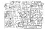
-The whole amp schematic.
There are two different schematics in the manual they both say “Note: this schematic diagram applies to units manufactured for the European market” the only difference I noticed in my quick glance is that one is multi voltage (I chose the schematic that is not multi voltage because the unit I have is 120v only).
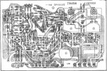
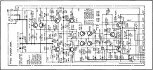
-The “p700” output circuit, board diagram and schematic.
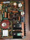
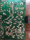
-The Front and back pictures of the output board.
-And here's the HiFi engine link where you can find the full service manual (if you have an account). https://www.hifiengine.com/manual_library/marantz/1150.shtml
I am seeking knowledge about a Marantz 1150 (not the D model). This amp is a friends, and they asked me to take a look at it. I have a rudimentary knowledge of electronics (mainly tinkering with them for fun) and can solder confidently.A bit of Context:
Here's the story of what happened. I did some work on the amp for my friend because one channel was fuzzy and cut in and out. Cleaning the pots and switches with contact cleaner fixed it right up, but I also found the main power switch was toast (literally melted) so I swapped it and the snubber out for a new replacement kit I got off Ebay. After that I held onto it for about a week or two using it as my daily amp to make sure everything was Peachy-Keen, it worked completely fine with zero issues.
Then about 2 months later, I was contacted again by my friend saying that “One channel is cracking really loud”. I visited his house the next day, yep it was undeniably crackling from the left channel; I agreed to take it home to figure out what was wrong. Disassembled it figuring it would be the contacts of the output relay (which I had just cleaned instead of the suggested route of just replacing it, as I have seen mentioned on forums). After futzing with the relay, I turned it on and… I got audio out of both channels (Sparking a moment of jubilation. I had found the issue) ... then the cracking came back, and the relay immediately turned off. After leaving it off for a while to cool down, I turned it back on and the output relay would not click on; “Ok” I thought “I'll disconnect the left output board and see if the relay turns on.” It did.
So, that leads us to today at which I have been trying to figure out what is wrong for the past week and have not made much progress.
Anyway, the gist of it is,
There is something wrong with the left channel's DC offset causing the protection relay to not turn on. I know it is a problem with the left channel and not the relay circuit because the right channel and protection circuit function fine when the left channel is unplugged (inside the amp, not at the output to the speakers). I am trying to figure out what would cause this. I have read it could be a “leaky” transistor; I have also heard that there is no way to test for this with a multimeter (which is about the most sophisticated testing equipment I have).
Penny for your thoughts? I am keen to figure this out so any guidance would be most appreciated. If y’all need any further, or more detailed information I am more than happy to oblige.
Here is what I have tested so far,
- Diode mode multimeter test on output transistors (while removed from their sockets); both read within spec.
- Basic board mounted test of all of the component's resistances compared against the functioning output board for the right channel. (I know this is not super reliable, but I wanted to test as much as I could without aimlessly De-soldering components,) Nothing varied much between the two, and there were not any shorts that I found.
- I should also mention I have found evidence of transistor H713 having been replaced at some point, the traces were lifted and replaced with wire. (there is also a sticker on the back saying it had work done by someone back in 1986)
The files below are as follows:
-The whole amp schematic.
There are two different schematics in the manual they both say “Note: this schematic diagram applies to units manufactured for the European market” the only difference I noticed in my quick glance is that one is multi voltage (I chose the schematic that is not multi voltage because the unit I have is 120v only).
-The “p700” output circuit, board diagram and schematic.
-The Front and back pictures of the output board.
-And here's the HiFi engine link where you can find the full service manual (if you have an account). https://www.hifiengine.com/manual_library/marantz/1150.shtml