

You are using an out of date browser. It may not display this or other websites correctly.
You should upgrade or use an alternative browser.
You should upgrade or use an alternative browser.
Cheap Chinese 6P3P kit
- Thread starter Big & Pink
- Start date

siliconray
Member
Thanks Sachin! I'm so happy that all the troubles are solved in the end!

bobrown14
Super Member
I think Not...One Red goes thru the Switch to the Rectifier, the other goes right to the Rectifier, and the Black goes to the AC Ground Lug, and to the PT Bolt...
Ok now I'm confused. my thought since I don't have the diagram for the PT is this:
IEC -Line side (hot) of IEC/fused to power switch to red wire from transformer
IEC - neutral side of IEC to switch to black primary
Earth ground (third prong) to chassis/earth
I got that....
extra red to rectifier? I dont got that???
Edit after sleeping on it: I've got 2 300V outputs from the tranny going to pin 4 & 6 on the rectifier and 2 5V heater wires going to pin 2 & 8 on the rectifier.
one red (input to tranny) to switch from AC/fused LINE (hot) and one black (tranny input beside the 2 red inputs) to switch then to the NEUTRAL line AC 120V, extra red going to??
I'm guessing here cause the tranny is not labeled (nothing but a smudge).
Okay... how about this hookup?
I could just run one red to the 120V line (hot) and one red to the 120V neutral, black to negative supply rail ... that sounds better to me. I'm used to seeing different color wires on the primary input.
Cheers,
Bob
Last edited:
bobrown14
Super Member
6P3P kits pics part 3
Ok got the transformer wire thing straightened out. I was trying to over think it a bit. I'm still not sure about the 0 black wire next to the 2 red inputs, I should think it goes to the CIRCUIT ground (negative post on the big cap). I need to think that thru a little bit. I hear ya's on the chassis (earth) ground but that seems wrong (dangerous) to me ...
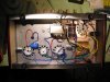
Any how here's some pics of all the wiring so far. Both reds to the switch and then a black and a red wire to the IEC socket (red to LINE and black to NEUTRAL). All the caps are in place and I'm getting ready to wire them up but I'm done for tonight. I gotta sleep on that black 0 wire from the primary side of the tranny.
Pic1 to 3 chassis layout with most of the positive rail in place, the black and yellow wires are the negative wires bundled together waiting for me to make up my mind on how I'm going to wire it. Thinking all that will go to the negative pin on the 470uF power supply cap. Straighten me out if I'm wrong.
Pic 4 is our cake from the weekend, after 12 years living with my SO we finally got married. Been there done that but hey .. her Mom is visiting from Russia so I thought it would be a good idea to jump the broom while she's here visiting. Mom is an electrical engineer, sharpened her teeth on tube gear in Russian tanks (night vision gear) and also in the nuclear military realm from which A LOT of good tubes are coming from out of Russia. I've asked her about old tubes and she mentioned the vintage tubes are getting more expensive. She also pretty much dismissed tube gear like what I'm building as "old technology and obsolete". I can't wait to fire this baby up and show her something else indeed. Notice the heart shaped blue and red wires going to the output tranny, that's my tribute to Anna, she's the best ...
Cheers,
Bob
Ok got the transformer wire thing straightened out. I was trying to over think it a bit. I'm still not sure about the 0 black wire next to the 2 red inputs, I should think it goes to the CIRCUIT ground (negative post on the big cap). I need to think that thru a little bit. I hear ya's on the chassis (earth) ground but that seems wrong (dangerous) to me ...
Any how here's some pics of all the wiring so far. Both reds to the switch and then a black and a red wire to the IEC socket (red to LINE and black to NEUTRAL). All the caps are in place and I'm getting ready to wire them up but I'm done for tonight. I gotta sleep on that black 0 wire from the primary side of the tranny.
Pic1 to 3 chassis layout with most of the positive rail in place, the black and yellow wires are the negative wires bundled together waiting for me to make up my mind on how I'm going to wire it. Thinking all that will go to the negative pin on the 470uF power supply cap. Straighten me out if I'm wrong.
Pic 4 is our cake from the weekend, after 12 years living with my SO we finally got married.
Been there done that but hey .. her Mom is visiting from Russia so I thought it would be a good idea to jump the broom while she's here visiting. Mom is an electrical engineer, sharpened her teeth on tube gear in Russian tanks (night vision gear) and also in the nuclear military realm from which A LOT of good tubes are coming from out of Russia. I've asked her about old tubes and she mentioned the vintage tubes are getting more expensive. She also pretty much dismissed tube gear like what I'm building as "old technology and obsolete". I can't wait to fire this baby up and show her something else indeed. Notice the heart shaped blue and red wires going to the output tranny, that's my tribute to Anna, she's the best ...Cheers,
Bob
Attachments




Congatulations, Mr. and Mrs. Brown!

apurcell22
Well-Known Member
Congrats Bob! I didn't think I would do it again, but got re hitched last August. This one brings home vinyl and tube gear to me, instead of just bleeding the account dry on who knows what.
Al
Al
bobrown14
Super Member
Congrats Bob! I didn't think I would do it again, but got re hitched last August. This one brings home vinyl and tube gear to me, instead of just bleeding the account dry on who knows what.
Al
Yeah right on. Anna helps me with gear too. She helped shlep some EV Sentry III speakers to the car and from the car to our 2nd floor listening room (165# speakers).. and the only real grief I get lately is about our listening room dismantled for re-fit and wants to set up a "temporary" rig while we work on the re-fit. Anna loves listening to music with me too and specially vinyl.
I should be testing my amp later tonight after I get home from work, I will finalize the wiring and plug in and test the power supply for proper voltages.
Cheers,
Bob
bobrown14
Super Member
It's Looking Good Bob....But, DO NOT TURN IT ON....Both LINE wires (RED) from the IEC go to One End of the Switch, Both Reds Into the PT from the Other...The Black from the PT goes to the IEC NEUTRAL....It is Not Switched....
Ok - switch/fuse on the LINE side... just attach both reds to the switch and run the LINE to them. Black tranny to the neutral side of the IEC. Right?
I'm a lefty.
Cheers,
Bob

sled108
Super Member
Both of the Power (Line) from the IEC Socket go to The Middle of the Switch, Both Reds on the PT go To the One END of the Switch (Not Side) into It...Black from the PT goes to Neutral (Ground) on the IEC Socket...The Rest of your Wiring Looks Great...Aww, Nice Heart there...
Watch that PT Bolt...It Might be Close....

Watch that PT Bolt...It Might be Close....
Attachments

Last edited:
bobrown14
Super Member
Both of the Power (Line) from the IEC Socket go to The Middle of the Switch, Both Reds on the PT go To the One END of the Switch (Not Side) into It...Black from the PT goes to Neutral (Ground) on the IEC Socket...The Rest of your Wiring Looks Great...Aww, Nice Heart there...
Watch that PT Bolt...It Might be Close....

Thanks Sled for the diagram, I got it. At some point I'm going to need tie back to that chassis ground from the circuit, correct? Would that be the negative terminal from the 330uf PSU cap??
Cheers,
Bob
bobrown14
Super Member
Ok I've got this amp wired and power to the rectifier tube glows.
I'm checking voltages with my DMM, here's some results:
B+ = 429v dC
330uf + leg = 429VdC
47uF + leg = 429VdC
Pin4 6P3 socket = 429VdC
22uF + leg = 429VdC
My thought is I want to see around 260VdC on the B+ - pretty hard to get 429V from a 330V winding unless I got some magic.
So I got something wrong in the wiring.
At the rectifier tube pin 4 & 6 (from 300V tap from transformer = 324VaC
At the rectifier tube pin 2 & 8 (should be from 5V heater) I've got 434Vdc (429V + 5V = 434V??)
429V seems high, where should I look for a wire in the wrong place?
Cheers,
Bob
I'm checking voltages with my DMM, here's some results:
B+ = 429v dC
330uf + leg = 429VdC
47uF + leg = 429VdC
Pin4 6P3 socket = 429VdC
22uF + leg = 429VdC
My thought is I want to see around 260VdC on the B+ - pretty hard to get 429V from a 330V winding unless I got some magic.
So I got something wrong in the wiring.
At the rectifier tube pin 4 & 6 (from 300V tap from transformer = 324VaC
At the rectifier tube pin 2 & 8 (should be from 5V heater) I've got 434Vdc (429V + 5V = 434V??)
429V seems high, where should I look for a wire in the wrong place?
Cheers,
Bob

shelly_d
Not An Audiophool
...
My thought is I want to see around 260VdC on the B+ - pretty hard to get 429V from a 330V winding unless I got some magic.
...
Not magic at all. It is all about the difference in AC RMS voltage and AC peak voltage. When a transformer is specified with voltage, it is specified with the RMS (Root Mean Square) voltage. That is the voltage that will provide reliable power dissipation numbers when doing power calculations. It is not however the very top of the sine wave. That is 1.414 times larger then the RMS value. Once rectified and filtered, the DC value you get is about the peak value minus any loses in the rectifier. So 330 x 1.414 = 466 V. Drop about 30 volts in the tube rectifier you are using and you get 436 V. Right in the ball park for your 429 V.
Shelly_D